Toshiba 50H81 Service Manual - Page 6
Picture Tube Components Adjustment - service mode
 |
View all Toshiba 50H81 manuals
Add to My Manuals
Save this manual to your list of manuals |
Page 6 highlights
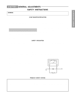
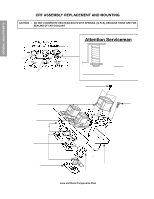
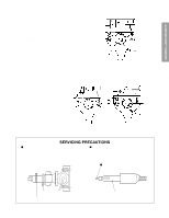
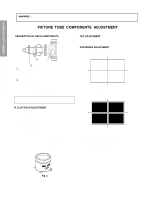
GENERAL ADJUSTMENTS SPECIFIC INFORMATIONS WARNING : BEFORE SERVICING THIS CHASSIS, READ THE "X-RAY RADIATION PRECAUTION", "SAFETY PRECAUTION" AND "PRODUCT SAFETY NOTICE" ON PAGE 3 OF THIS MANUAL. PICTURE TUBE COMPONENTS ADJUSTMENT DESCRIPTION OF NECK COMPONENTS TILT ADJUSTMENT Rotate R, G, B deflection yoke so that picture becomes horizon, then fasten screw. CENTERING ADJUSTMENT 1. Stretch a thread between two center of screen edge (top and bottom, left and right). ᕃ ᕄ ᕃ Deflection yoke and convergence yoke The position on the neck is required most front (CRT funnel side) and the screw is fastened after rotating yoke adjusting picture tilt. ᕄ Centering magnet After adjusting picture tilt, picture position is finally fixed by this magnet. In order to get maximum margin of user convergence control for center of screen, this magnet have to be used for center convergence adjustment. PREPARATION Operate the receiver for at least 5 minutes. R, G, B FOCUS ADJUSTMENT 1. Before adjusting the R, G, B FOCUS, remove the 4 screws of Lens Assembly which is fixed on the CRT Assembly. (See page 4.) Then turn around the Lens Assembly by 180˚ to adjust the fastening screw (Fig. a) and fasten the 4 screws to secure Lens Assembly. 2. Select the adjustment mode. (See page 9.) 3. Press "7" button to display the built-in cross-hatch. 4. Press "0" and "RTN" buttons to make the picture a single Red color. 100 button to erase Red color 0 button to erase Green color CH RTN button to erase Blue color 5. Loosen the fasten screw and adjust Red lense focus to best focusing point of picture center. Then fasten the screw. (See Fig. a.) 2. Select the adjustment mode. 3. Press TV/VIDEO button on the Remote Control to display the white cross-bar. 4. Perform VCEN adjustment. (See page 11.) 5. Adjust G centering magnet so that the cross-bar pattern center comes to screen center. 6. Perform HEIGHT adjustment . (See page 12.) 7. Perform VERT. LINEARITY adjustment. 8. Perform WIDTH adjustment. (See page 11.) 9. Check whole quality of green line. 10. Adjust R, B centering magnet so that the cross-bar pat- tern center comes to screen center. Fig. a 6. Adjust FOCUS VR "R" of FOCUS PACK to find best fo- cusing point of picture center. 7. Repeat steps 3 to 5 for Green and Blue colors. - 6 -
-
 1
1 -
 2
2 -
 3
3 -
 4
4 -
 5
5 -
 6
6 -
 7
7 -
 8
8 -
 9
9 -
 10
10 -
 11
11 -
 12
12 -
13
-
14
-
15
-
16
-
17
-
18
-
19
-
20
-
21
-
22
-
23
-
24
-
25
-
26
-
27
-
28
-
29
-
30
-
31
-
32
-
33
-
34
-
35
-
36
-
37
-
38
-
39
-
40
-
41
-
42
-
43
-
44
-
45
-
46
-
47
-
48
-
49
-
50
-
51
-
52
-
53
-
54
-
55
-
56
-
57
-
58
-
59
-
60
-
61
-
62
-
63
-
64
-
65
-
66
 |
 |
