Toshiba 50H81 Service Manual - Page 11
Electrical Adjustment, Adjustment Procedure - wiring
 |
View all Toshiba 50H81 manuals
Add to My Manuals
Save this manual to your list of manuals |
Page 11 highlights
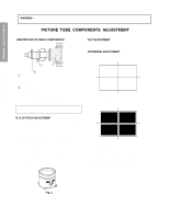
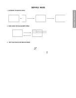
GENERAL ADJUSTMENTS SPECIFIC INFORMATIONS ELECTRICAL ADJUSTMENT ITEM ƒH (free-running frequency of Hor. oscillator) ADJUSTMENT PROCEDURE 1. Receive NTSC signal. 2. Short the terminal "TP +9V " and the terminal " TP (Free run) " on the signal board with a jumper wire. 3. Connect the probe of frequency counter to the lead of R426 and GND. 4. Adjust the frequency to "33.75±0.2 kHz" by turning R4034 on DPC Board. 5. Disconnect the shorted wire, then confirm that the picture is synchronized. VERTICAL POSITION (VCEN) 1. Receive NTSC signal. 2. Connect he probe of digital voltmeter to TP-V and TP-G on SIGNAL Board. 3. Call up the adjustment mode display, then select the item VCEN. 4. Press the VOLUME s or t button to get the voltage 0±10 mV. PICTURE POSITION (HPOS) 1. Receive NTSC signal. 2. Call up the adjustment mode display. 3. Select the item "HPOS", and adjust the data to "80H". 4. Adjust the picture position alternately by turning CENTERING MAGNETS for proper picture position. 5. Check the picture with off-air signal. WIDTH (WID) 1. Receive NTSC signal. 2. Select the "FULL" mode by PIC SIZE button on Remote Control. 3. Call up the adjustment mode display, then select the item WID. 4. Press the VOLUME s or t button to get the picture so that left and right eddes of video signal begin to lack. 5. Press the VOLUME s button to advance the data by 8 steps. NOTE: Check the horizontal picture position is correct. SUB-BRIGHTNESS (BRTC) 1. Constrict the picture height until the vertical retrace line appears adjusting the HEIGHT control on the MAIN board. 2. Adjust the CONTRAST to the minimum and BRIGHTNESS to the center. 3. Enter the service mode, then select "BRTC" register. 4. Adjust the data value so the belt of vertical retrace line just disappear. 5. Adjust the CONTRAST for the desired contrast. 6. Adjust the HEIGHT control. Vertical retrace line SUB-COLOR (SCOL) 1. Receive color-bar signal from color-bar generator. 2. Adjust the BRIGHTNESS and CONTRAST to the center (RESET status). 3. Connect oscilloscope to TP501on the MAIN board. Blue 4. Enter the service mode, then select "SCOL". 5. Adjust the data value to achieve 1.8V0-p of blue bar on scope. Magenta 6. Check the picture with off-air signal. 0 3 (1.8V0-P) 2 - 11 -
-
 1
1 -
2
-
3
-
4
-
5
-
 6
6 -
 7
7 -
 8
8 -
 9
9 -
 10
10 -
 11
11 -
 12
12 -
 13
13 -
 14
14 -
 15
15 -
 16
16 -
17
-
18
-
19
-
20
-
21
-
22
-
23
-
24
-
25
-
26
-
27
-
28
-
29
-
30
-
31
-
32
-
33
-
34
-
35
-
36
-
37
-
38
-
39
-
40
-
41
-
42
-
43
-
44
-
45
-
46
-
47
-
48
-
49
-
50
-
51
-
52
-
53
-
54
-
55
-
56
-
57
-
58
-
59
-
60
-
61
-
62
-
63
-
64
-
65
-
66
 |
 |
