Toshiba 50H81 Service Manual - Page 5
Servicing Precautions - convergence board
 |
View all Toshiba 50H81 manuals
Add to My Manuals
Save this manual to your list of manuals |
Page 5 highlights
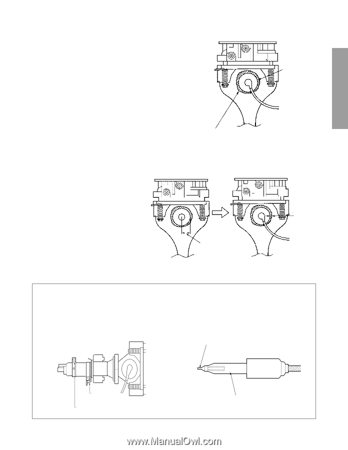
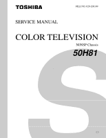
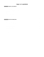
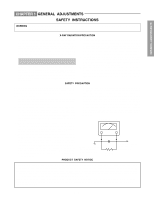
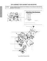
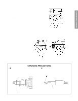
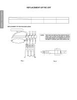
GENERAL ADJUSTMENTS TO REMOVE CRT (Same procedure for R, G, B) 1. Remove CRT DRIVE Board, S. V. M. COIL and DEF. YOKE from CRT. 2. Remove Lens Assembly. 3. Detach CRT Anode Cap from CRT. 4. Remove CRT Assembly from CRT Mounting. CRT REPLACEMENT (Same procedure for R, G, B) Reverse the removal procedures except the followings. 1. Anode Cable should be replaced with new one. See "SERVICING PRECAUTIONS" shown below. 2. Install silicon (T461B) to the CRT, replace the Anode cable and put enough silicon again on around the Anode Cap as illustrated. CAUTION: Align the Anode cable as illustrated on page 4. ADJUSTING PROCEDURE IN REPLACING CRT 1. R.G.B. FOCUS ADJUSTMENT (page 6.) 2. PICTURE TILT ADJUSTMENT (page 6.) 3. USER CONVERGENCE CENTER CHECK (See owner's manual.) 4. CENTERING ADJUSTMENT (page 6.) 5. CONVERGENCE ADJUSTMENT (page 13.) 6. WHITE BALANCE ADJUSTMENT (page 12.) Adjustments are complete. Anode Cap Silicon (On shaded area) TSE3843W #23960136 15 ~ 25 mm 2 ~ 5 mm SPECIFIC INFORMATIONS SERVICING PRECAUTIONS I Do not use a magnetized screw driver for screws of Deflection Yoke and Velocity Modulation Coil to avoid magnetization of electron gun. Magnetization of electron gun will degrade basic function and result in unbalance of right and left shift of user static convergence, and result in no variable quantity. I When replacing the anode cap assembly (CRT) or anode lead assembly (F.B.T.), remove the anode lead holder from old one and attach the holder again to new anode lead. I Check the point of anode lead in a straight line, if it is winding, please revise it. Screw for D.Y Screw for SVM coil - 5 - Anode lead holder
-
 1
1 -
 2
2 -
 3
3 -
 4
4 -
 5
5 -
 6
6 -
 7
7 -
 8
8 -
 9
9 -
 10
10 -
 11
11 -
12
-
13
-
14
-
15
-
16
-
17
-
18
-
19
-
20
-
21
-
22
-
23
-
24
-
25
-
26
-
27
-
28
-
29
-
30
-
31
-
32
-
33
-
34
-
35
-
36
-
37
-
38
-
39
-
40
-
41
-
42
-
43
-
44
-
45
-
46
-
47
-
48
-
49
-
50
-
51
-
52
-
53
-
54
-
55
-
56
-
57
-
58
-
59
-
60
-
61
-
62
-
63
-
64
-
65
-
66
 |
 |