Toshiba DP30A Instruction Manual - Page 36
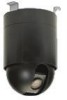
Fig-7, Fig-8 - ik camera
 |
UPC - 032017546370
View all Toshiba DP30A manuals
Add to My Manuals
Save this manual to your list of manuals |
Page 36 highlights
(IK-DP30A dome base install) (11) Attach the video cable (included with the dome w accessories) to the video connector of a dome base. [Note: Do not connect a thick coaxial cable to a dome camera. There is a possibility of e damaging a connector. Be sure to use the cable included in the dome accessories.] (12) Communication cables are directly inserted in q the terminal of the dome base. (13) Tighten the screw to secure the dome base to the housing. Fig-5 qwe FIg-5 (IK-DP30A dome drive install) (14) After setting up DIP-SW in the top of the dome (See 8.Switch setting), connect the support wire to the hook of the dome base. Fig-6 q (15) To lock the dome drive to the dome base, line up the notch with the label and turn to the right with both q hands. Fig-6 w Ensure that the location of the notch (position of yellow paint) on the w dome base and the location of the installation label on the dome drive are aligned. Fig-6 (JK-H01A dome cover install) (16) To lock the dome cover, insert the support wire and turn to the right with both hands. Fig-7, Fig-8 Fig-7 (17) The installation is complete. Downloaded from www.Manualslib.com manuals search engine - 36 - Fig-8
-
 1
1 -
2
-
3
-
4
-
5
-
6
-
7
-
8
-
9
-
10
-
11
-
12
-
13
-
14
-
15
-
16
-
17
-
18
-
19
-
20
-
21
-
22
-
23
-
24
-
25
-
26
-
27
-
28
-
29
-
30
-
 31
31 -
 32
32 -
 33
33 -
 34
34 -
 35
35 -
 36
36 -
 37
37 -
 38
38 -
 39
39 -
 40
40
 |
 |
