Toshiba Satellite 4090XDVD Replacement Instructions - Page 3
Satellite, Series
 |
View all Toshiba Satellite 4090XDVD manuals
Add to My Manuals
Save this manual to your list of manuals |
Page 3 highlights
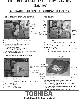
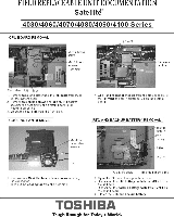
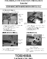
FIELD REPLACEABLE UNIT DOCUMENTATION Satellite' 4030/4060/4070/4080/4090/4100 Series MODEM REMOVAL TOP COVER REMOVAL M25. black sci modem board screws ht2.6s6 black screw Modem cable laid idlwer screws Mak brass screw 1.'="StMinlgetil rerOrni7' 'ne " braes 2 Lift up the right side of the modem board and remove it Som. syMem board. 3. Disconnect Pie modem cable from PJ2 on the modem TOP COVER REMOVAL FL cable PJd .16 black 1 Turn the compute 5Nd bla =ew s side down and remove the r-°1, 1g.5'SIrbleanc -3 M2.5•6 black scews ion -5 M2.5v1 black scr e ftrIT "" I s't of the computer -1 .16 black screw : erk PJ3 id- Ler ape bl Top cover PJ7 steh black Membrane P.1 screw switch cable 2. Turn the campus right side up and open the display panel 3. Remove A. Mfix14 black screws and one 10.5361 black screw securing the top cover. A Disconnect the following five cables: - LCD cable Dorn PO - FL cable Dorn PM - Membrane switch cable Dorn PRO Lert speaker cable Dorn PM Right speaker cable Dorn PH ble Display assembly 5 Lift up the Lack and lea of the top cover about Pgfit rttli;h1V2) cto'' C1neVIrrI tIte wc'oVo?) *cm the top cover. 6. Rotate the top cover and display assembly forward to release the right atch. TOSHIBA Tough Enough for Today's World.
-
 1
1 -
 2
2 -
 3
3 -
 4
4 -
 5
5 -
 6
6 -
 7
7 -
 8
8 -
 9
9
 |
 |
