Toshiba Satellite 4090XDVD Replacement Instructions - Page 7
Toshiba Satellite 4090XDVD Manual
 |
View all Toshiba Satellite 4090XDVD manuals
Add to My Manuals
Save this manual to your list of manuals |
Page 7 highlights
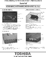
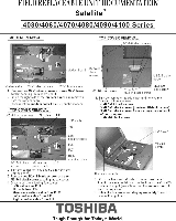
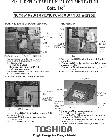
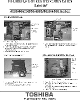
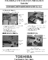
FIELD REPLACEABLE UNIT DOCUMENTATION Satellite' 4030/4060/4070/4080/4090/4100 Series SENSOR AND SOUND BOARD REMOVAL a oblea P.500 tt .1g* V2.5.4 brass screw 1 bf:ncrodnnect the sound cable from IMMO on the sound 2 Remove one Ift2.5x4 brass screw securing sound hoard 3 Lift out the sound board 13.3 TFT DISPLAY MASK REMOVAL FL INVERTER AND 13.3 TFT LCD REMOVAL frf2.56 brass screws Display mask LCD module LCD module cable FL cable 15c2r.5..4 brass HV cable FL inverter hoard Mast seals I Remove two mask seals a! Me bottom corners of the dftPlay aSSembly 2 Remove Iwo el1.5e6 Mass IltIOWS 3 'Clem ate 22 latch., serunng Me display mask. MICI r rtr0ftDIrftjfti177peTe7aNes=gt inta top six latches lo Inv five latches on the right and left sides, vorlmy ti the six bottom latches t. Remora tape antl brass screw ."""x5 "cur' 2. Carefully lift up Dm FL inverter board a. disc nnact Me FL Inverter cable from CHI and the V cable from CH 3. Lemora four In.,. brims screws securing the CD modle. 4. ?ara,,ftgota::na LCD module from right to left 5. Disconnect the LCD cable from the LCD module and remove the LCD from the computer TOSHIBA Tough Enough for Today's World.
-
 1
1 -
 2
2 -
 3
3 -
 4
4 -
 5
5 -
 6
6 -
 7
7 -
 8
8 -
 9
9
 |
 |
