Toshiba Satellite L510 PSLQ0C-02R00C Users Manual Canada; English - Page 134
Insert the memory module into the connector on the computer. Press
 |
View all Toshiba Satellite L510 PSLQ0C-02R00C manuals
Add to My Manuals
Save this manual to your list of manuals |
Page 134 highlights
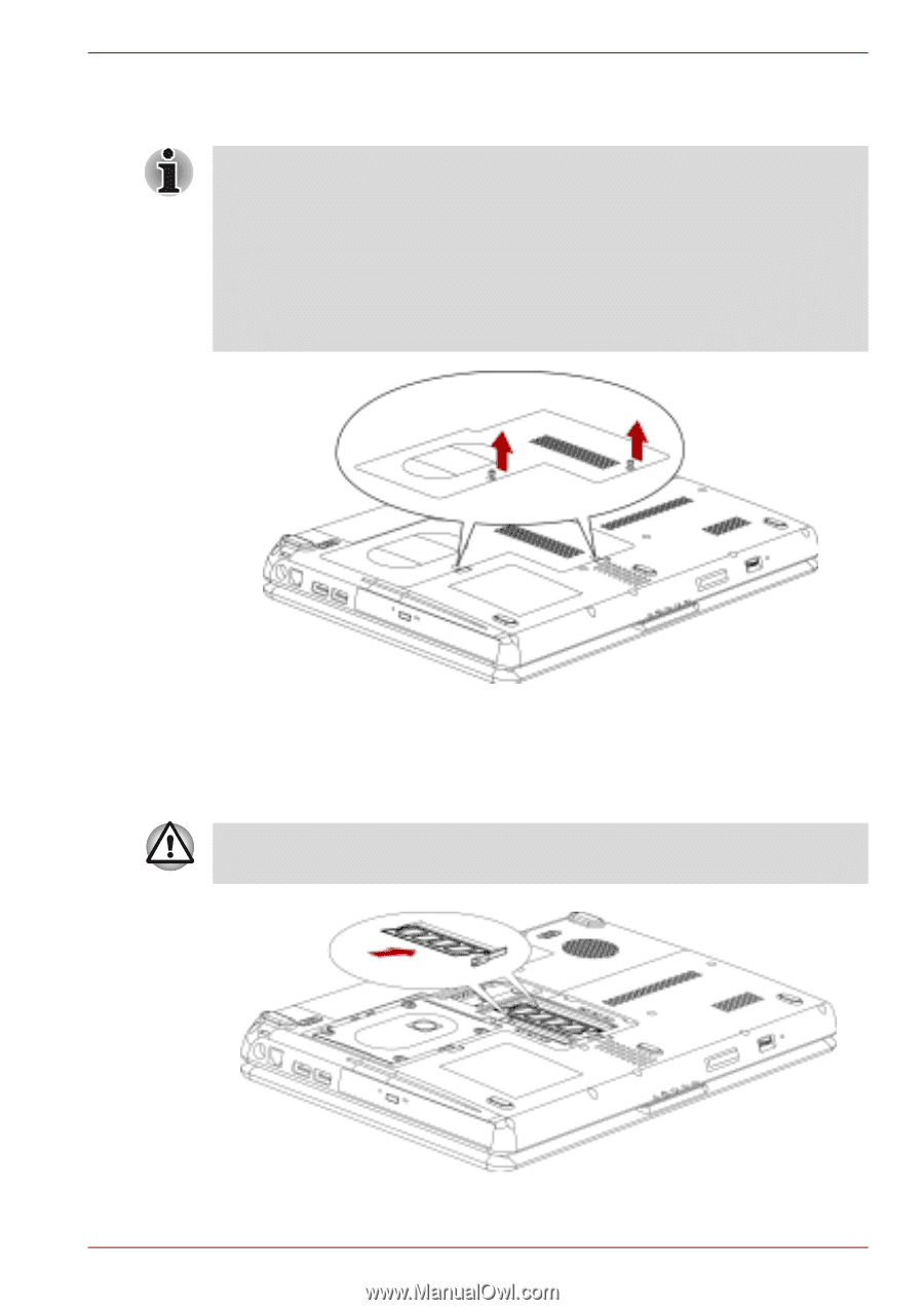
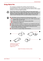
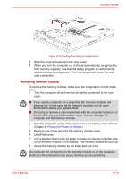
Optional Devices 4. Remove one screw securing the memory module cover. 5. Lift off the cover. ■ Use a point size 0 Phillips screwdriver. ■ Insert the two memory modules of the same specifications and capacity into Slot A and Slot B respectively. The computer will operate in dual channel mode. You can access the inserted memory modules efficiently in dual channel. ■ Slot A is reserved for main memory; Slot B is for expanded memory. If only one memory module is installed, use Slot A. Slot A is lower than Slot B. Figure 8-8 Removing the cover 6. Insert the memory module into the connector on the computer. Press the module carefully and firmly to ensure a solid connection. 7. Push the module down so that it lies flat and is secured by two latches. Do not touch the connectors on the memory module or on the computer. Debris on the connectors may cause memory access problems. User's Manual Figure 8-9 Inserting the memory module 8-9
-
 1
1 -
2
-
3
-
4
-
5
-
6
-
7
-
8
-
9
-
10
-
11
-
12
-
13
-
14
-
15
-
16
-
17
-
18
-
19
-
20
-
21
-
22
-
23
-
24
-
25
-
26
-
27
-
28
-
29
-
30
-
31
-
32
-
33
-
34
-
35
-
36
-
37
-
38
-
39
-
40
-
41
-
42
-
43
-
44
-
45
-
46
-
47
-
48
-
49
-
50
-
51
-
52
-
53
-
54
-
55
-
56
-
57
-
58
-
59
-
60
-
61
-
62
-
63
-
64
-
65
-
66
-
67
-
68
-
69
-
70
-
71
-
72
-
73
-
74
-
75
-
76
-
77
-
78
-
79
-
80
-
81
-
82
-
83
-
84
-
85
-
86
-
87
-
88
-
89
-
90
-
91
-
92
-
93
-
94
-
95
-
96
-
97
-
98
-
99
-
100
-
101
-
102
-
103
-
104
-
105
-
106
-
107
-
108
-
109
-
110
-
111
-
112
-
113
-
114
-
115
-
116
-
117
-
118
-
119
-
120
-
121
-
122
-
123
-
124
-
125
-
126
-
127
-
128
-
 129
129 -
 130
130 -
 131
131 -
 132
132 -
 133
133 -
 134
134 -
 135
135 -
 136
136 -
 137
137 -
 138
138 -
 139
139 -
140
-
141
-
142
-
143
-
144
-
145
-
146
-
147
-
148
-
149
-
150
-
151
-
152
-
153
-
154
-
155
-
156
-
157
-
158
-
159
-
160
-
161
-
162
-
163
-
164
-
165
-
166
-
167
-
168
-
169
-
170
-
171
-
172
-
173
-
174
-
175
-
176
-
177
-
178
-
179
-
180
-
181
-
182
-
183
-
184
-
185
-
186
-
187
-
188
-
189
-
190
 |
 |