Toshiba Satellite Pro P300 PSPCDA-01N00D Users Manual Canada; English - Page 54
Underside, Cooling Vents, Memory Module, Wireless LAN Cover, Hard Disk Cover, Battery Pack Lock
 |
View all Toshiba Satellite Pro P300 PSPCDA-01N00D manuals
Add to My Manuals
Save this manual to your list of manuals |
Page 54 highlights
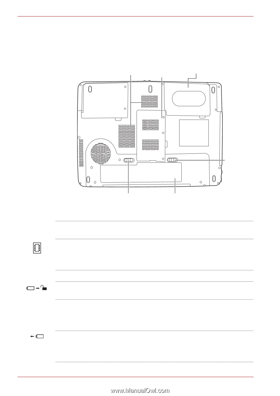
The Grand Tour Underside The following figure shows the underside of the computer. Make sure the display is closed before turning over your computer. Cooling Memory Module Vents and Wireless LAN Cover Hard Disk Cover Battery Release Latch Battery Pack Lock Battery Pack The underside of the computer Cooling Vents Cooling vents help prevent the CPU from overheating. Memory Module and Wireless LAN Cover This cover protects two memory module sockets -one or two modules are pre-installed. Refer to the Memory expansion section in Chapter 8, Optional Devices. Hard Disk Cover This cover protects the hard disk. Battery Pack Lock Slide this lock to prepare the battery pack for removal. Battery Pack The battery pack powers the computer when the AC adaptor is not connected. For detailed information on the battery pack, refer to Chapter 6, Power and Power-Up Modes. Battery Release Latch Slide and hold this latch to release the battery pack for removal. For detailed information on removing the battery pack, refer to Chapter 6, Power and Power-Up Modes. 2-6 User's Manual
-
 1
1 -
2
-
3
-
4
-
5
-
6
-
7
-
8
-
9
-
10
-
11
-
12
-
13
-
14
-
15
-
16
-
17
-
18
-
19
-
20
-
21
-
22
-
23
-
24
-
25
-
26
-
27
-
28
-
29
-
30
-
31
-
32
-
33
-
34
-
35
-
36
-
37
-
38
-
39
-
40
-
41
-
42
-
43
-
44
-
45
-
46
-
47
-
48
-
 49
49 -
 50
50 -
 51
51 -
 52
52 -
 53
53 -
 54
54 -
 55
55 -
 56
56 -
 57
57 -
 58
58 -
 59
59 -
60
-
61
-
62
-
63
-
64
-
65
-
66
-
67
-
68
-
69
-
70
-
71
-
72
-
73
-
74
-
75
-
76
-
77
-
78
-
79
-
80
-
81
-
82
-
83
-
84
-
85
-
86
-
87
-
88
-
89
-
90
-
91
-
92
-
93
-
94
-
95
-
96
-
97
-
98
-
99
-
100
-
101
-
102
-
103
-
104
-
105
-
106
-
107
-
108
-
109
-
110
-
111
-
112
-
113
-
114
-
115
-
116
-
117
-
118
-
119
-
120
-
121
-
122
-
123
-
124
-
125
-
126
-
127
-
128
-
129
-
130
-
131
-
132
-
133
-
134
-
135
-
136
-
137
-
138
-
139
-
140
-
141
-
142
-
143
-
144
-
145
-
146
-
147
-
148
-
149
-
150
-
151
-
152
-
153
-
154
-
155
-
156
-
157
-
158
-
159
-
160
-
161
-
162
-
163
-
164
-
165
-
166
-
167
-
168
-
169
-
170
-
171
-
172
-
173
-
174
-
175
-
176
-
177
-
178
-
179
-
180
-
181
-
182
-
183
-
184
-
185
-
186
-
187
-
188
-
189
-
190
-
191
-
192
-
193
-
194
-
195
-
196
-
197
-
198
-
199
-
200
-
201
-
202
-
203
-
204
-
205
-
206
-
207
-
208
 |
 |