Toshiba TLP-S40 User Manual - Page 11
Connection - projector
 |
View all Toshiba TLP-S40 manuals
Add to My Manuals
Save this manual to your list of manuals |
Page 11 highlights
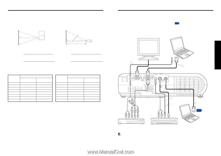
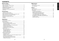
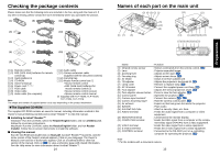
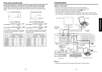
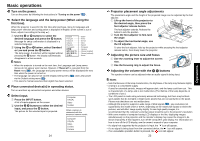
Placement (Continued) Projection Distance and Screen Size (with optical zooming) Use the figures, tables, and formulas below to determine the screen size and projection distance. (Screen sizes are approximate values for full-size picture with no keystone adjustment) Screen As seen from above As seen from the side Lens center 90 90 a For TLP-T70M/T71M For TLP-T60M/T61M/S40/S41 projection size (inches) - 1.547 projection size (inches) - 1.4285 a (min length) = a (min length) = 26.44 30.68 projection size (inches) - 1.2907 projection size (inches) - 1.1908 a (max length) = 22.06 a (max length) = 25.574 a is the distance (m) between the lens and a is the distance (m) between the lens and the screen, and corresponds to a range of the screen, and corresponds to a range of 1.45 m to 11.29 m. 1.26 m to 9.73 m. screen size (cm) 40 (102) 60 (152) 80 (203) 100 (254) 150 (381) 200 (508) 250 (635) 300 (762) projection distance a(m) min length max length (zooming max) (zooming min) 1.45 2.21 2.97 3.72 5.61 7.51 9.40 11.29 1.75 2.66 3.57 4.47 6.74 9.01 11.27 - screen size (cm) 40 (102) 60 (152) 80 (203) 100 (254) 150 (381) 200 (508) 250 (635) 300 (762) projection distance a(m) min length max length (zooming max) (zooming min) 1.26 1.52 1.91 2.30 2.56 3.08 3.21 3.86 4.84 5.82 6.47 7.77 8.10 9.73 9.73 - 20 Connection Before connection • Read the owner's manual of the device to connect to the projector. • Some types of computer cannot be used or connected to this projector. Check for an RGB output terminal, supported signal p.46 , etc. • Turn off the power of both devices before connecting. • The figure below is a sample connection. This does not mean that all of these devices can or must be connected simultaneously. (Dotted lines mean items can be exchanged.) CRT monitor, etc. Computer Audio cable (for computer) (supplied) AUDIO MONITOR To audio output COMPUTER( Y/PB/PR ) VIDEO VIDEO S-VIDEO CONTROL To RGB output RGB cable (supplied) Monitor cable Mini D-sub 15P-BNC (not supplied) To audio output White (L) Red (R) Audio cable (supplied) To Y/CB/CR output Green (Y) Blue (CB), Red (CR) Yellow (to video output) To audio Conversion output adapter White (L) BNC-pin Red (R) (not supplied) S-Video cable (not supplied) Video cable (supplied) To S-Video output Control cable p48 To RS-232C terminal DVD player VCR Computer (for control) Note • The AUDIO terminal can be used with all the devices for input terminal. 21 Preparations
-
 1
1 -
2
-
3
-
4
-
5
-
 6
6 -
 7
7 -
 8
8 -
 9
9 -
 10
10 -
 11
11 -
 12
12 -
 13
13 -
 14
14 -
 15
15 -
 16
16 -
17
-
18
-
19
-
20
-
21
-
22
-
23
-
24
-
25
-
26
 |
 |