Toshiba TLP-S40 User Manual - Page 9
Names of each part on the document camera, Names of each part on the control panel and remote - projector manual
 |
View all Toshiba TLP-S40 manuals
Add to My Manuals
Save this manual to your list of manuals |
Page 9 highlights
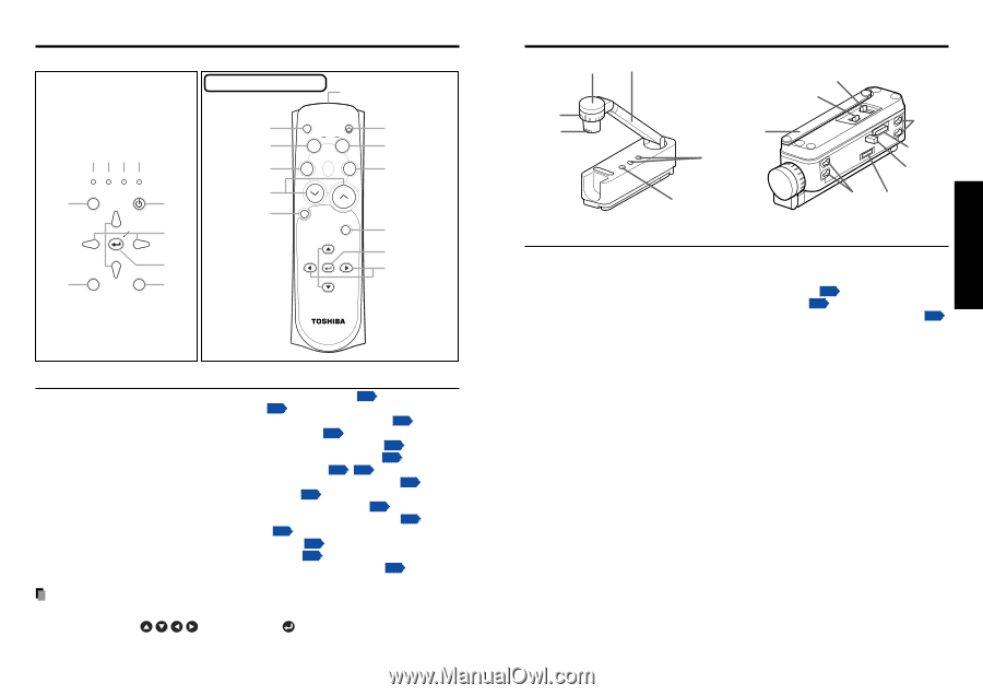
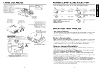
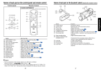
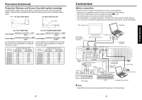
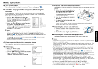
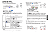
Names of each part on the control panel and remote control Control panel Remote Control CLASS 1 LED PRODUCT Remote control transmitter (7) (8) (9) (10) FAN TEMP LAMP ON (2) INPUT ON / STANDBY ZOOM + (1) VOL. - MENU (6) VOL. + (3) AUTO KEYSTONE AUTO SET ZOOM - (5) (4) (15) (3) (11) (13) (14) CALL ON/ STANDBY KEYSTONE AUTO SET MUTE FREEZE RESIZE CANCEL INPUT ZOOM + VOL.- MENU VOL.+ ZOOM - (1) (4) (12) (2) (5) (6) Name (1) ON/STANDBY button (2) INPUT button (3) AUTO KEYSTONE button (4) AUTO SET button (5) MENU button (6) Selection buttons (7) FAN indicator (8) TEMP indicator (9) LAMP indicator (10) ON indicator (11) MUTE button (12) FREEZE button (13) RESIZE buttons (14) CANCEL button (15) CALL button : Main Function : Turns the power on/off (standby). p.22 : Selects input. p.24 : Adjusts keystone (trapezoidal distortion). p.27 : Sets up image and mode. p.26 : Displays menus and makes selections. p.31 : Menu selections and adjustments, etc. p.31 : Displays cooling fan mode. p.23 p.42 : Lights when internal temperature too high. p.42 : Displays lamp mode. p.23 : Displays whether power is on or off. p.22 : Cuts off the picture and sound temporarily. p.28 : Pauses image. p.28 : Enlarges picture size. p.29 : Exiting the operation. p.30 : Displays the information on the screen. p.30 Notes • For the remainder of this manual, buttons are referred to as follows: Selection buttons ⇒ ; MENU button ⇒ • For further information of the mouse remote control supplied with the TLP-T60M, TLP- T61M, TLP-T70M, TLP-T71M, see the Owner's Manual of the Mouse Remote Control. 16 Names of each part on the document camera (models with a document camera) (1) (4) (2) (3) (12) (13) (8) (7) (5) (11) (10) (6) (8) (9) Name (1) Camera head (2) Camera lens (3) Focus ring (4) Camera arm (5) CAMERA GAIN buttons (6) CAMERA button (7) Tip resistant bar (8) Stay mounting holes (9) Camera output terminal (CAMERA OUT) (10) Lock bar (11) Connector (12) Connect lever (13) Lock lever : Function : Document camera. : Shooting lens for the document camera. : Adjusts the focus. : Adjusts the shooting angle. p.36 : Adjusts the camera gain. p.37 : Toggles between the camera input and previous input. p.36 : Pulled out when a camera is used separated from the projector. : Aligns with the projector's stay. : Connected to the accessory camera cable when a camera is used separated from the projector. : Locked to the projector. : Camera signal is output. : Connector is connected to the projector. : Used when the camera is disconnected from the projector. 17 Preparations
-
 1
1 -
2
-
3
-
 4
4 -
 5
5 -
 6
6 -
 7
7 -
 8
8 -
 9
9 -
 10
10 -
 11
11 -
 12
12 -
 13
13 -
 14
14 -
15
-
16
-
17
-
18
-
19
-
20
-
21
-
22
-
23
-
24
-
25
-
26
 |
 |