Toshiba Tecra A50-A PT645C-04W00W Users Manual Canada; English - Page 39
Underside, Battery lock, Battery release latch, Docking port
 |
View all Toshiba Tecra A50-A PT645C-04W00W manuals
Add to My Manuals
Save this manual to your list of manuals |
Page 39 highlights
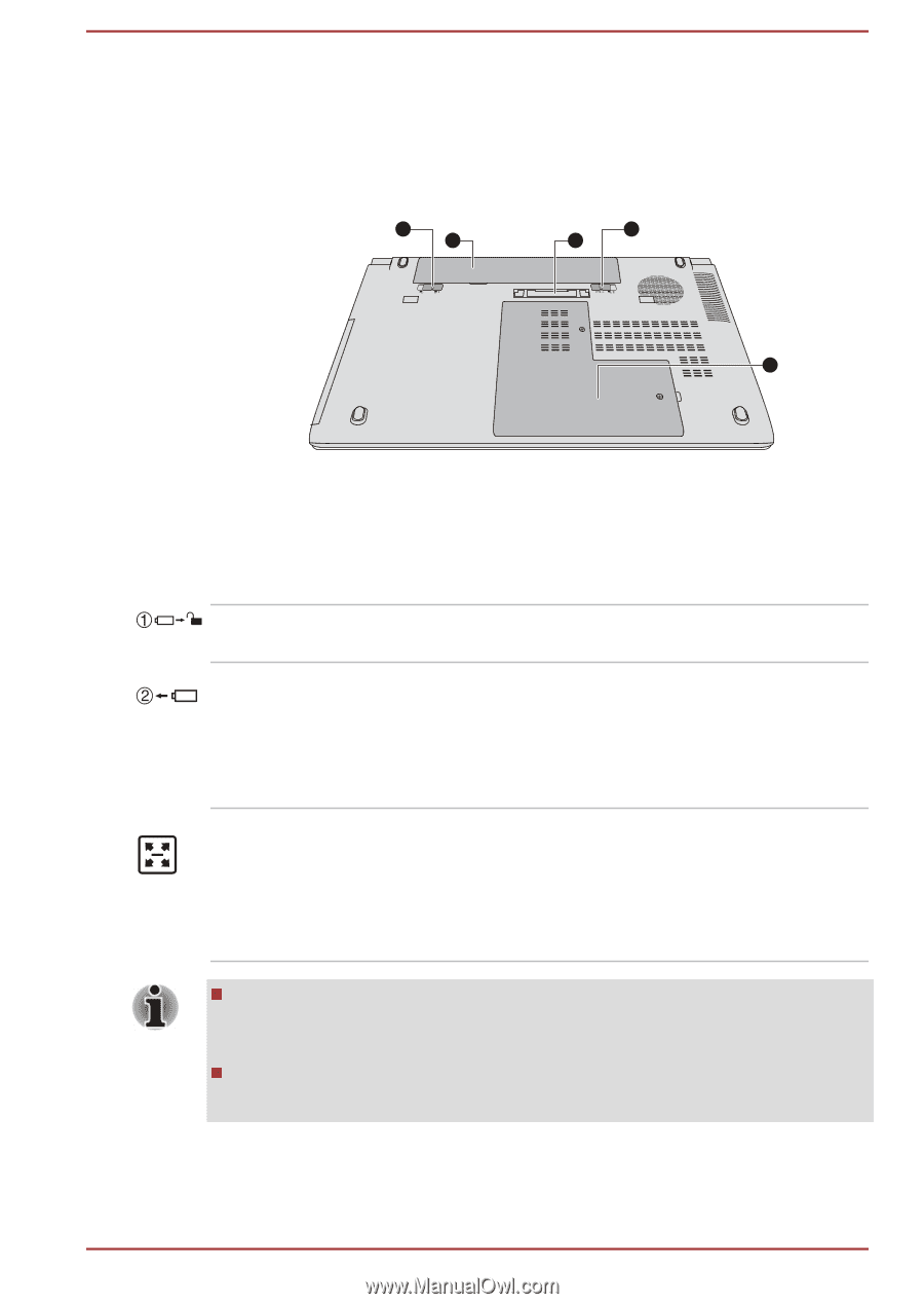
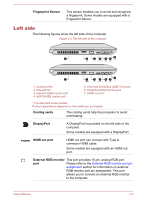
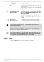
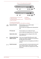
Underside The following figures show the underside of the computer. You should ensure that the display is closed before the computer is turned over to avoid causing any damage. Figure 3-5 The underside of the computer 1 3 2 4 5 1. Battery lock 2. Battery release latch 3. Battery pack 4. Docking port* 5. Memory module slot * Provided with some models. Product appearance depends on the model you purchased. Battery lock Slide the battery lock to release the battery pack ready for removal. Battery release latch Slide and hold this latch into its "Unlock" position in order to release the battery pack for removal.For more detailed information on removing the battery pack please refer to the Battery section. Docking port This port enables connection of an optional TOSHIBA Hi-Speed Port Replicator III 180W/ 120W described in TOSHIBA Hi-Speed Port Replicator III 180W/120W. Some models are equipped with a Docking port. Only the TOSHIBA Hi-Speed Port Replicator III 180W or 120W is applicable with this Docking port. Do not attempt to use any other Port Replicator. Keep foreign objects out of the docking port. A pin or similar object can damage the computer's circuitry. User's Manual 3-7
-
 1
1 -
2
-
3
-
4
-
5
-
6
-
7
-
8
-
9
-
10
-
11
-
12
-
13
-
14
-
15
-
16
-
17
-
18
-
19
-
20
-
21
-
22
-
23
-
24
-
25
-
26
-
27
-
28
-
29
-
30
-
31
-
32
-
33
-
 34
34 -
 35
35 -
 36
36 -
 37
37 -
 38
38 -
 39
39 -
 40
40 -
 41
41 -
 42
42 -
 43
43 -
 44
44 -
45
-
46
-
47
-
48
-
49
-
50
-
51
-
52
-
53
-
54
-
55
-
56
-
57
-
58
-
59
-
60
-
61
-
62
-
63
-
64
-
65
-
66
-
67
-
68
-
69
-
70
-
71
-
72
-
73
-
74
-
75
-
76
-
77
-
78
-
79
-
80
-
81
-
82
-
83
-
84
-
85
-
86
-
87
-
88
-
89
-
90
-
91
-
92
-
93
-
94
-
95
-
96
-
97
-
98
-
99
-
100
-
101
-
102
-
103
-
104
-
105
-
106
-
107
-
108
-
109
-
110
-
111
-
112
-
113
-
114
-
115
-
116
-
117
-
118
-
119
-
120
-
121
-
122
-
123
-
124
-
125
-
126
-
127
-
128
-
129
-
130
-
131
-
132
-
133
-
134
-
135
-
136
-
137
-
138
-
139
-
140
-
141
-
142
-
143
-
144
-
145
-
146
-
147
-
148
-
149
-
150
 |
 |