Toshiba Tecra M5-S5231 Resource Guide for Tecra M5 - Page 27
with its connector. Position the module toward the socket
 |
View all Toshiba Tecra M5-S5231 manuals
Add to My Manuals
Save this manual to your list of manuals |
Page 27 highlights
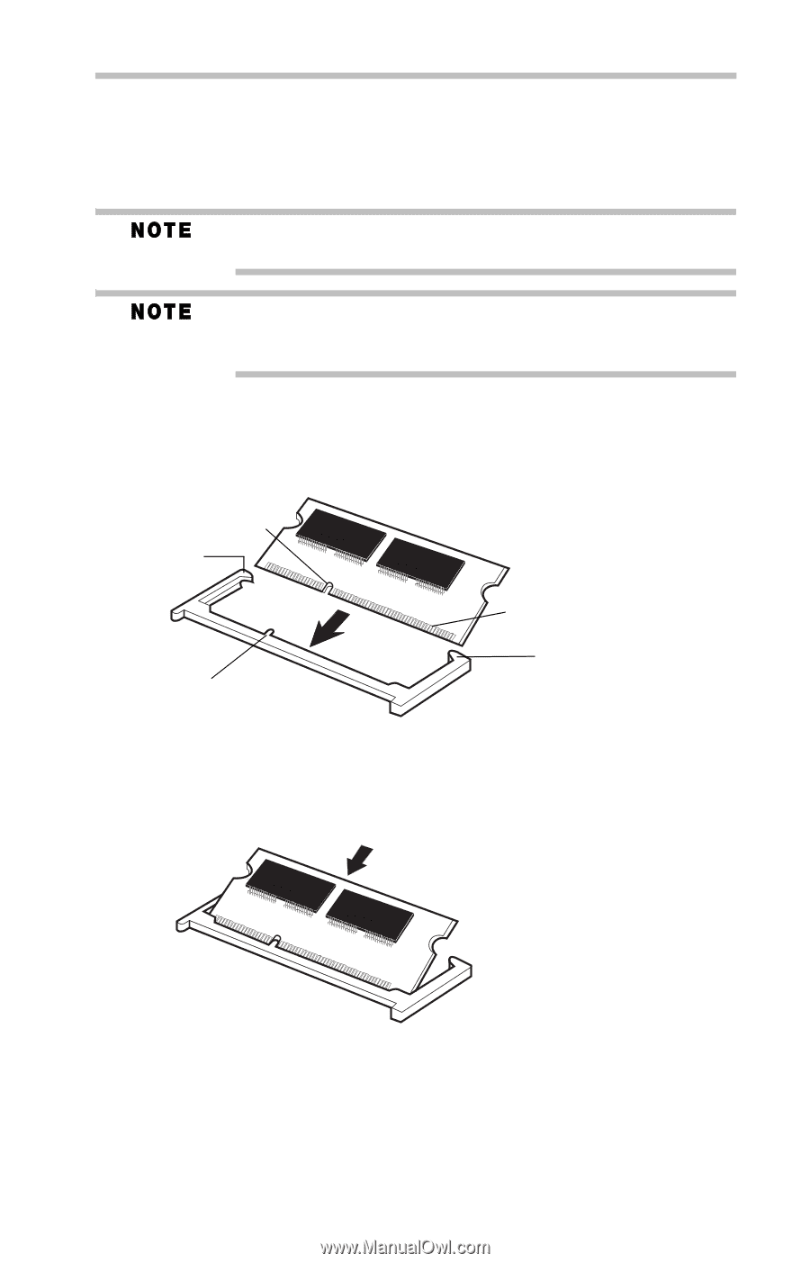
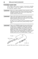
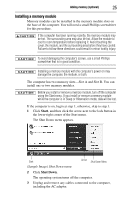
Adding memory (optional) 27 9 Carefully remove the new memory module from its antistatic packaging, without touching its connector. 10 Locate an empty memory module slot on the underside of the computer. If no memory slot is available, you must remove a module by performing steps 2-3 of "Removing a memory module" on page 29. If your system has the memory modules stacked on top of one another, you must remove the top module before removing/installing the bottom module. 11 Pick up the memory module by its sides, avoiding any contact with its connector. Position the module toward the socket, aligning the connector's notch with the matching key in the socket. notch latch connector latch key (Sample Illustration) Aligning the memory module with the socket 12 Firmly press the memory module into the memory slot's socket at approximately a 30-degree angle (to the horizontal surface of the computer). (Sample Illustration) Inserting the memory module into the socket
-
 1
1 -
2
-
3
-
4
-
5
-
6
-
7
-
8
-
9
-
10
-
11
-
12
-
13
-
14
-
15
-
16
-
17
-
18
-
19
-
20
-
21
-
 22
22 -
 23
23 -
 24
24 -
 25
25 -
 26
26 -
 27
27 -
 28
28 -
 29
29 -
 30
30 -
 31
31 -
 32
32 -
33
-
34
-
35
-
36
-
37
-
38
-
39
-
40
-
41
-
42
-
43
-
44
-
45
-
46
-
47
-
48
-
49
-
50
-
51
-
52
 |
 |