Tripp Lite SMARTINT3000VS Owner's Manual for SMARTINT2200VS/SMARTINT3000VS UPS - Page 5
Optional Installation, Basic Operation - inverter
 |
View all Tripp Lite SMARTINT3000VS manuals
Add to My Manuals
Save this manual to your list of manuals |
Page 5 highlights
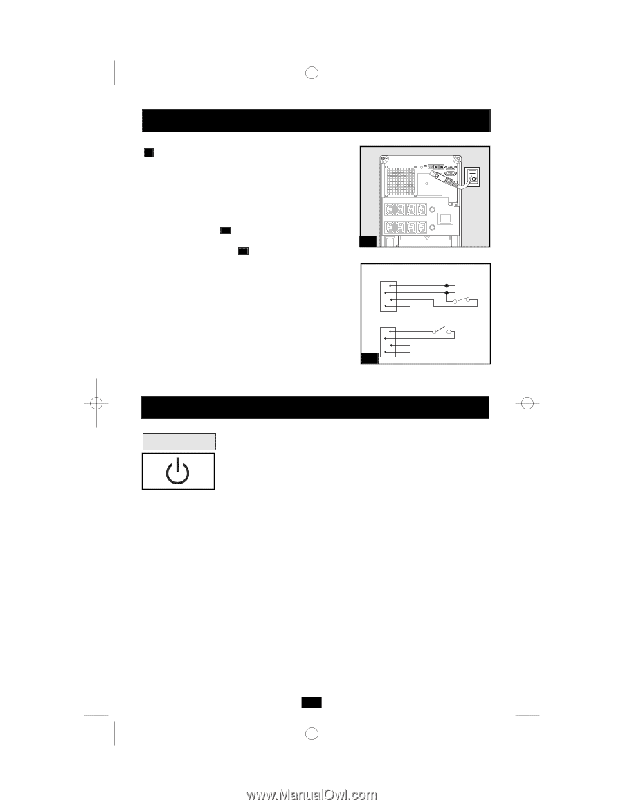
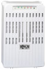
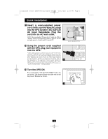
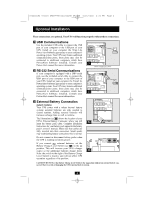
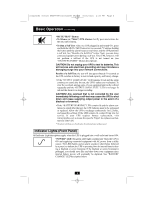
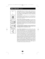
200404080 932245 SMARTINT22003000VS OM.qxd 5/26/2004 4:26 PM Page 5 Optional Installation 4 EPO Port Connection This optional feature is only for those applications which require connection to a facility's Emergency Power Off (EPO) circuit. When the UPS is connected to this circuit, it enables emergency shutdown of the UPS's inverter. Using the cable provided, connect the EPO port of your UPS (see 4a ) to a user-supplied normally closed or normally open switch according to the circuit diagram (see 4b ). The EPO port is not a phone line surge suppressor; do not connect a phone line to this port. 4a OPTION 1: USER SUPPLIED NORMALLY CLOSED SWITCH RJ11 PLUG 5 4 3 2 NO CONNECTION 4-5 JUMPER N.C. EPO SWITCH OPTION 2: USER SUPPLIED NORMALLY OPEN SWITCH RJ11 PLUG 4b 5 4 3 2 NO CONNECTION N.O. EPO SWITCH Basic Operation Buttons "ON/OFF/STANDBY" Button • To turn the UPS ON: with the UPS plugged into a live AC wall outlet,* press and hold the ON/OFF/STANDBY button for one second.** Release the button. If utility power is absent, you can "cold-start" the UPS (i.e.: turn it ON and supply power for a limited time from its batteries***) by pressing and holding the ON/OFF/STANDBY button for one second.** • To turn the UPS OFF: with the UPS ON and receiving utility power, press and hold the ON/OFF/STANDBY button for one second.** Then unplug the UPS from the wall outlet. The UPS will be completely OFF. * After you plug the UPS into a live AC outlet, the UPS (in "Standby" mode) will automatically charge its batteries, but will not supply power to its outlets until it is turned ON. ** The alarm will beep once briefly after the indicated interval has passed. *** If fully charged. 5
-
 1
1 -
 2
2 -
 3
3 -
 4
4 -
 5
5 -
 6
6 -
 7
7 -
 8
8 -
 9
9 -
 10
10 -
 11
11 -
12
-
13
-
14
-
15
-
16
-
17
-
18
-
19
-
20
-
21
-
22
-
23
-
24
-
25
-
26
-
27
-
28
-
29
-
30
-
31
-
32
-
33
-
34
-
35
-
36
-
37
-
38
-
39
-
40
-
41
-
42
-
43
-
44
 |
 |