Tripp Lite SU5000RT4UHV Owner's Manual for SmartOnline Single-Phase 5kVA-6kVA - Page 12
Optional Connection - power supply
 |
View all Tripp Lite SU5000RT4UHV manuals
Add to My Manuals
Save this manual to your list of manuals |
Page 12 highlights
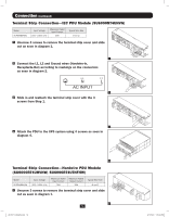
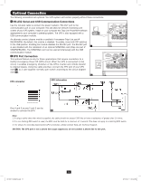
Optional Connection The following connections are optional. Your UPS system will function properly without these connections. 1 RS-232 Serial and USB Communication Connections Use the included cable to connect the power module's "RS-232" port to the communication port on your computer. This will allow full network monitoring and control of your UPS system. Install on your computer the Tripp Lite PowerAlert software appropriate to your computer's operating system. The UPS is also equipped with a USB communication module. An alternate contact closure module is available if necessary (Tripp Lite part # RELAYIOMINI). By default, this module is disabled. To enable, move both DIP switches to the USB position. Enabling this module disables the RS-232 port. The RS-232 port is also disabled with the installation of an optional SNMP/Web card (Tripp Lite part # 1 SNMPWEBCARD). The SNMP/Web card can be used simultaneously with the USB communication module. 2 EPO Port Connection This optional feature is only for those applications that require connection to a facility's Emergency Power Off (EPO) circuit. When the UPS is connected to this circuit, it enables emergency shutdown of the UPS's inverter and inhibits transfer to internal bypass. Using the cable provided, connect the EPO port of your UPS (see 2a) to a user-supplied normally open switch according to the circuit diagram (see 2b). 2a EPO connector EPO Information Pins 4 and 5 or pins 2 and 3 can be shorted to activate the EPO. 2b Note: 1. If using a cable other than what is supplied, the cable should not exceed 350 feet or have a resistance of greater than 10 ohms. 2. If a non-latching EPO switch is used, the EPO must be held for a minimum of 1 second. This does not apply to a latching EPO switch. 3. For setup of a normally closed-switch EPO connection, please contact Tripp Lite Technical Support. CAUTION: The EPO port is not a phone line surge suppressor; do not connect a phone line to this port. 12 201207113 933070.indb 12 9/17/2012 1:20:03 PM
-
 1
1 -
2
-
3
-
4
-
5
-
6
-
 7
7 -
 8
8 -
 9
9 -
 10
10 -
 11
11 -
 12
12 -
 13
13 -
 14
14 -
 15
15 -
 16
16 -
 17
17 -
18
-
19
-
20
-
21
-
22
-
23
-
24
-
25
-
26
-
27
-
28
-
29
-
30
-
31
-
32
-
33
-
34
-
35
-
36
-
37
-
38
-
39
-
40
-
41
-
42
-
43
-
44
-
45
-
46
-
47
-
48
-
49
-
50
-
51
-
52
-
53
-
54
-
55
-
56
-
57
-
58
-
59
-
60
-
61
-
62
-
63
-
64
-
65
-
66
-
67
-
68
-
69
-
70
-
71
-
72
-
73
-
74
-
75
-
76
-
77
-
78
-
79
-
80
-
81
-
82
-
83
-
84
-
85
-
86
-
87
-
88
-
89
-
90
-
91
-
92
-
93
-
94
-
95
-
96
-
97
-
98
-
99
-
100
-
101
-
102
-
103
-
104
-
105
-
106
-
107
-
108
-
109
-
110
-
111
-
112
-
113
-
114
-
115
-
116
 |
 |
