Tripp Lite SU5000RT4UHV Owner's Manual for SmartOnline Single-Phase 5kVA-6kVA - Page 14
WARNING! High voltage! Risk of electrical shock - battery replacement
 |
View all Tripp Lite SU5000RT4UHV manuals
Add to My Manuals
Save this manual to your list of manuals |
Page 14 highlights
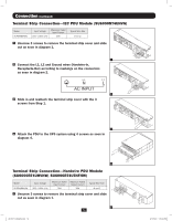
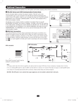
Hot-Swap Power Module Replacement* WARNING! For qualified service personnel only. Failure to follow the bypass procedure completely will not adequately power down the UPS, resulting in the continued risk of death or injury from pontential contact with high voltage. The UPS and detachable PDU are extremely heavy. This procedure requires several people to perform. The UPS system includes an independent, detachable PDU with a Bypass Switch. This switch allows qualified service personnel to remove the detachable PDU from the UPS for routine maintenance without disrupting power to connected loads. While this switch is set to "BYPASS", connected equipment will receive unfiltered AC mains power. But the equipment will not receive battery power in the event of a blackout. * See manual included with SU12KRT4UHW Parallel PDU for Bypass. UPS Removal (6kVA Single UPS Power Module Configurations Only) STEP 1. Disable PowerAlert and disconnect the SNMP or serial USB communication cables from the communication ports A on the UPS. STEP 2. Press UPS's "OFF" button B , if the UPS is powered, until you hear a beep and see a "BYPASS MODE" message shown in its LCD Display C on the front of the power module. You will be prompted to enter "BYPASS MODE". Press UPS "OFF" button again to activate "BYPASS MODE". STEP 3. Turn the detachable PDU's Bypass Switch D to "BYPASS" on the rear of the UPS PDU. STEP 4. If an external battery module is connected to the UPS E , disconnect it from the UPS. The UPS is now safely powered down and it can be detached from the PDU to perform maintenance/replacement. STEP 5. Remove the four screws that secure the front mounting ears of your UPS to the rack. With the PDU still attached, move the UPS system and PDU forward in the rack slightly (approximately 4 inches), being sure that both components remain adequately supported by the UPS's rackmount support rails. STEP 6. At the rear of the UPS, remove the four screws that hold the detachable PDU to the UPS that is being serviced. With an assistant holding the front of the UPS in place, carefully detach the PDU from the rear of the UPS and rest it on the UPS support rails. Remove the UPS power module from the front of the rack. WARNING! High voltage! Risk of electrical shock! A RS-232 PARALLEL EPO RS-232 USB C B NORMAL BY PASS Step 2 E Steps 1, 3 & 4 D Step 5 201207113 933070.indb 14 Step 6 14 9/17/2012 1:20:05 PM
-
 1
1 -
2
-
3
-
4
-
5
-
6
-
7
-
8
-
 9
9 -
 10
10 -
 11
11 -
 12
12 -
 13
13 -
 14
14 -
 15
15 -
 16
16 -
 17
17 -
 18
18 -
 19
19 -
20
-
21
-
22
-
23
-
24
-
25
-
26
-
27
-
28
-
29
-
30
-
31
-
32
-
33
-
34
-
35
-
36
-
37
-
38
-
39
-
40
-
41
-
42
-
43
-
44
-
45
-
46
-
47
-
48
-
49
-
50
-
51
-
52
-
53
-
54
-
55
-
56
-
57
-
58
-
59
-
60
-
61
-
62
-
63
-
64
-
65
-
66
-
67
-
68
-
69
-
70
-
71
-
72
-
73
-
74
-
75
-
76
-
77
-
78
-
79
-
80
-
81
-
82
-
83
-
84
-
85
-
86
-
87
-
88
-
89
-
90
-
91
-
92
-
93
-
94
-
95
-
96
-
97
-
98
-
99
-
100
-
101
-
102
-
103
-
104
-
105
-
106
-
107
-
108
-
109
-
110
-
111
-
112
-
113
-
114
-
115
-
116
 |
 |
