Troy-Bilt CSV 070 Service Manual - Page 13
Screws, Engine, Nozzle, Lower housing, Nut & bolt, See
 |
View all Troy-Bilt CSV 070 manuals
Add to My Manuals
Save this manual to your list of manuals |
Page 13 highlights
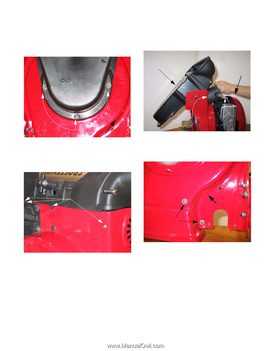
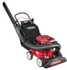
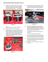
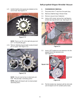
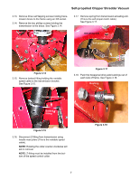
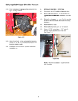
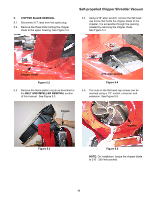
Self-propelled Chipper Shredder Vacuum 4.7. Use a 1/4" wrench to remove the three Screws securing the black plastic nozzle to the lower housing. They are accessible from underneath. See Figure 4.7. 4.9. Tilt top of black plastic nozzle toward the engine to remove. This will allow the safety gate to pass by the hose opening freely. See Figure 4.9. Black plastic nozzle Nozzle Engine 1/4" Screws Figure 4.7 4.8. Four phillips head screws secure the front of the nozzle to the frame. Remove them. See Figure 4.8. Safety gate within vacuum tube Figure 4.9 4.10. Remove all of the fasteners holding the lower housing to the upper housing. See Figure 4.10. Nozzle Mounting Screws Nut & bolt Lower housing Figure 4.8 Figure 4.10 NOTE: There is a variety of nuts, bolts, and selftapping screws holding the two housings together. 9
-
 1
1 -
2
-
3
-
4
-
5
-
6
-
7
-
 8
8 -
 9
9 -
 10
10 -
 11
11 -
 12
12 -
 13
13 -
 14
14 -
 15
15
 |
 |