Troy-Bilt CSV 070 Service Manual - Page 8
Safety switch, Belt tensioner, Spring, Low speed position, Sheaves together, Sheaves apart
 |
View all Troy-Bilt CSV 070 manuals
Add to My Manuals
Save this manual to your list of manuals |
Page 8 highlights
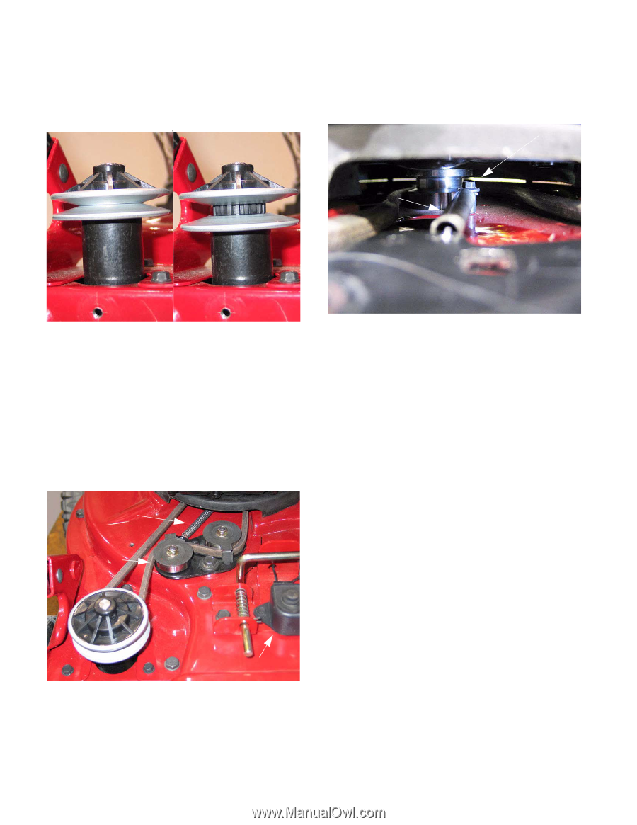
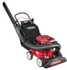
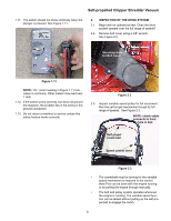
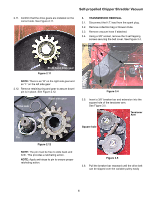
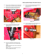
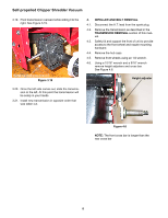
Self-propelled Chipper Shredder Vacuum 2.4. Watch the travel of the variable speed sheave (pulley) on the input shaft. It may be necessary to remove the belt to confirm that the variable speed sheave has full travel. See Figure 2.4. Low speed position: Sheaves together High speed position: Sheaves apart 2.7. If the idler pulleys do not react properly, confirm that the spring is properly attached to tension bracket and spring anchor bolt. See Figure 2.7. Spring anchor bolt Spring Figure 2.4 NOTE: Belt removed for clarity in figure 2.4 2.5. Confirm that the belt is routed properly. 2.6. Watch the reaction of the two idler pulleys. If the bracket that they are mounted to does not pivot freely in response to the changes in belt tension created by the movement of the variable speed sheaves, the full range of speeds will not be available, and accelerated component wear will result. See Figure 2.6. Spring Belt tensioner Figure 2.7 2.8. If the belt and pulley system works properly, turning the variable speed sheave on the transmission input shaft, but fails to drive the wheels when the self propel bail is lifted, then there may be a problem in one of three areas: • The cable that connects the bail to the clutch mechanism. • The final drive gears within the wheels. • There may be an internal problem with the dog clutch in the transmission. If there is an internal transmission problem, replace the transmission. 2.9. To check the final drive gears, remove both rear hubcaps. Remove the rear wheels using a 9/16" wrench and a 1/2" wrench. 2.10. Check the condition of the teeth on the back of the wheel. Safety switch Figure 2.6 4
-
 1
1 -
2
-
 3
3 -
 4
4 -
 5
5 -
 6
6 -
 7
7 -
 8
8 -
 9
9 -
 10
10 -
 11
11 -
 12
12 -
 13
13 -
14
-
15
 |
 |