Troy-Bilt CSV 070 Service Manual - Page 5
Self-Propelled Chipper Shredder Vacuum, 1. Safety Switch, ABOUT
 |
View all Troy-Bilt CSV 070 manuals
Add to My Manuals
Save this manual to your list of manuals |
Page 5 highlights
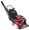
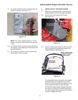
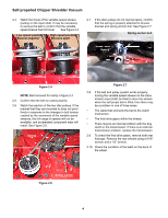
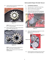
Self-propelled Chipper Shredder Vacuum Self-propelled Chipper Shredder Vacuum ABOUT THIS SECTION: In model year 2000, MTD introduced a vertical crankshaft lawn vacuum with a 22" clearing width and the capacity to shred small yard debris. Since it's introduction, the product has been enhanced with a removable vacuum hose. The latest product improvement is the addition of a self-propell feature. NOTE: The equipment that was used to write this section was a prototype. There may be subtle differences between prototypes and production equipment. For the sake of orientation: • All engine controls are located on the engine.(i.e. choke and throttle) • The variable speed lever is on the left side of the handle. This is NOT a throttle control. • The variable speed lever will not move easily unless the engine crankshaft is rotating. Do NOT force the lever. • The control Bail mounted to the handlebar engages the drive system. It does NOT turn-off the engine like the blade control handle on a mower. 1. SAFETY SWITCH The safety switch is located at the rear of the unit. The intent is to make sure that it will not run without a collection bag or blower chute in place. The safety switch is a normally closed switch. This means that when the bag or chute are not present, the plunger will be up, and the contacts within the switch will be closed. The switch is mounted to the upper impeller housing assembly. A magneto primary wire connects to one terminal of the safety switch. The other terminal of the safety switch is connected to a ground wire. When the collection bag or blower chute is on the unit, the safety switch plunger will be depressed, and the contacts will be separated. NOTE: A multimeter or continuity tester can be used for this section. 1.1. Confirm that the metal tab on the collection bag or chute depress the plunger far enough to open the contacts in the switch. 1.2. Disconnect the switch from the magneto primary wire at the bullet connector. 1.3. Check for continuity through the switch, from the bullet connector to ground. See Figure 1.3. Figure 1.3 NOTE: In figure 1.3, the meter shows continuity (near 0 ohms). This engine will not start even though the bag is in place. 1
-
 1
1 -
 2
2 -
 3
3 -
 4
4 -
 5
5 -
 6
6 -
 7
7 -
 8
8 -
 9
9 -
 10
10 -
 11
11 -
12
-
13
-
14
-
15
 |
 |
