Troy-Bilt CSV 070 Service Manual - Page 7
Inspection of the Drive System, Belt Cover - chipper shredder vacuum
 |
View all Troy-Bilt CSV 070 manuals
Add to My Manuals
Save this manual to your list of manuals |
Page 7 highlights
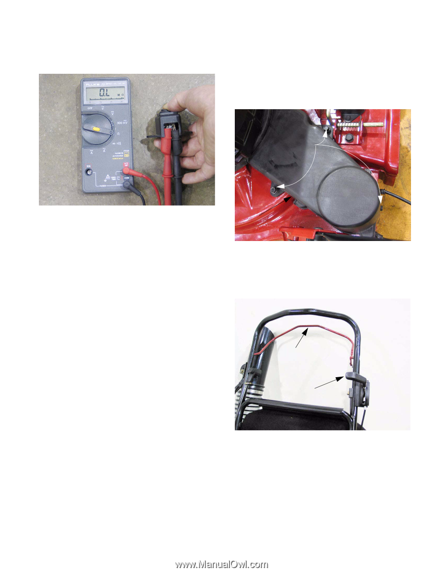
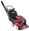
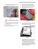
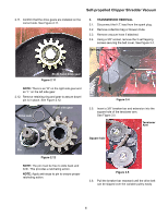
Self-propelled Chipper Shredder Vacuum 1.11. The switch should not show continuity when the plunger is pressed. See Figure 1.11. 2. INSPECTION OF THE DRIVE SYSTEM 2.1. Begin with an operational test. Does the drive system operate over the full range of speeds? 2.2. Remove belt cover using a 3/8" wrench. See Figure 2.2. Mounting Bolts for Belt Cover Figure 1.11 NOTE: "OL" meter reading in Figure 1.11 indicates no continuity. Other meters may read near 1 ohm. 1.12. If the switch works correctly, but does not ground the magneto, the problem lies in the wiring or the ground connection. 1.13. Do not return a machine to service unless this safety feature works correctly. Belt Cover Figure 2.2 2.3. Inspect variable speed pulley for full movement. Run the self propel mechanism though its full range of speeds. See Figure 2.3. NOTE: clutch cable connects to front hole in bail. Self propel clutch bail Speed control lever Figure 2.3 • The crankshaft must be turning for the variable speed mechanism to respond to the control lever.This can be done with the engine running or by pulling the engine through manually. • The belt and pulley system operates whenever the engine is running. The variable speed function can be tested without pulling up the self-propel bail to engage the clutch. 3
-
 1
1 -
 2
2 -
 3
3 -
 4
4 -
 5
5 -
 6
6 -
 7
7 -
 8
8 -
 9
9 -
 10
10 -
 11
11 -
 12
12 -
13
-
14
-
15
 |
 |