Troy-Bilt CSV 070 Service Manual - Page 6
See - chipper shredder
 |
View all Troy-Bilt CSV 070 manuals
Add to My Manuals
Save this manual to your list of manuals |
Page 6 highlights
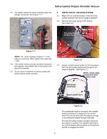
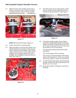
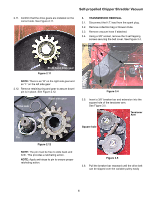
Self-propelled Chipper Shredder Vacuum 1.4. If slight pressure on the tab breaks continuity, adjusting the tab by bending it downward will enable the switch to work correctly. See Figure 1.4. 1.8. If the switch fails to ground the magneto, identify if the switch itself is at fault, or if a bad connection exists between the switch and ground. NOTE: A lock tab secures the plug to the switch. The switch must be removed to reach the lock tab. 1.9. Remove the switch from the frame using a 5/16" wrench or driver. See Figure 1.9. Figure 1.4 1.5. If the switch does not break the ground path (meter reading: near 1.0 ohms, or "OL" indicates open contacts, breaking ground path) when the plunger is pressed, replace the switch. 1.6. The switch should complete a path from the magneto to ground when the plunger is up. See Figure 1.6. Figure 1.9 1.10. Test the switch independently. It should show continuity with the plunger up. See Figure 1.10. Figure 1.6 NOTE: If the switch fails to ground out the magneto when the plunger is up, it would be possible to run the engine without a blower chute or collector bag in place. This is unsafe. 1.7. 2 Figure 1.10
-
 1
1 -
 2
2 -
 3
3 -
 4
4 -
 5
5 -
 6
6 -
 7
7 -
 8
8 -
 9
9 -
 10
10 -
 11
11 -
 12
12 -
13
-
14
-
15
 |
 |
