Troy-Bilt Pro-Line CRT Service Manual - Page 25
Transmission Assembly,
 |
View all Troy-Bilt Pro-Line CRT manuals
Add to My Manuals
Save this manual to your list of manuals |
Page 25 highlights
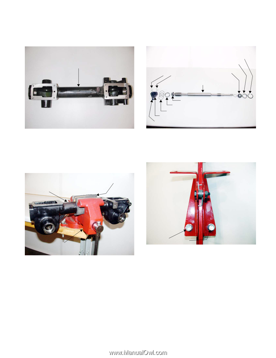
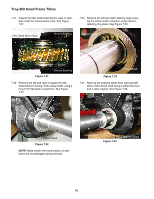
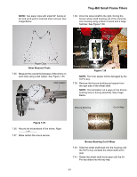
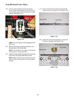
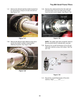
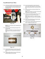
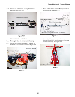
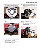
7.61. Inspect the transmission housing for wear or damage. See Figure 7.61. Troy-Bilt Small Frame Tillers 8.3. Make certain all the drive shaft components are accounted for. See Figure 8.3. Transmission Housing Hex Flange Screws Snap Ring Race Tapered Roller Bearing Drive Shaft Assembly Figure 7.61 8. TRANSMISSION ASSEMBLY: 8.1. Thoroughly clean the transmission housing. 8.2. Set the transmission housing in a vice that is lined with a protective material. See Figure 8.2. Transmission Housing Protective Material Tapered Roller Bearing Race Shims Rear Bearing Cap Short Hex Flange Screw and Lock Washer Figure 8.3 8.4. Locate both hex flange screws that were securing the left and right hood brackets to the transmission assembly. See Figure 8.4. Vice Figure 8.2 Hex Flange Screws Figure 8.4 21
-
 1
1 -
2
-
3
-
4
-
5
-
6
-
7
-
8
-
9
-
10
-
11
-
12
-
13
-
14
-
15
-
16
-
17
-
18
-
19
-
 20
20 -
 21
21 -
 22
22 -
 23
23 -
 24
24 -
 25
25 -
 26
26 -
 27
27 -
 28
28 -
 29
29 -
 30
30 -
31
-
32
-
33
-
34
-
35
-
36
-
37
-
38
-
39
-
40
-
41
-
42
 |
 |