Troy-Bilt Pro-Line CRT Service Manual - Page 41
Reverse Idler Pulley Assembly, Transmission Pulley,
 |
View all Troy-Bilt Pro-Line CRT manuals
Add to My Manuals
Save this manual to your list of manuals |
Page 41 highlights
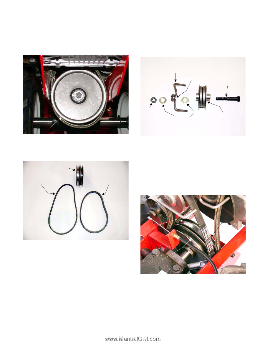
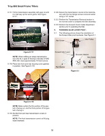
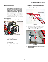
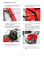
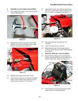
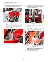
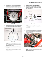
3.8. Remove the hex screw and belleville washer securing the transmission pulley to the drive shaft assembly using a 1/2" socket. See Figure 3.8. Troy-Bilt Small Frame Tillers 4. REVERSE IDLER PULLEY ASSEMBLY: 4.1. The following picture shows the reverse idler assembly components in their correct orientation. See Figure 4.1. Hex Screw Belleville Washer Belt Guide Open Center Hex Screw Transmission Pulley Figure 3.8 3.9. Remove the transmission pulley and drive belts from the drive shaft assembly. See Figure 3.9. Transmission Pulley Inside-Out Reverse Drive Belt Forward Drive Belt Lock Nut Reverse Idler Pulley Flat Washers Figure 4.1 NOTE: The open center of the reverse belt guide, for the reverse idler, is position down during assembly. 5. TRANSMISSION PULLEY: 5.1. The following picture shows the V-pulley section, and the flat pulley sections of the transmission pulley. See Figure 5.1. Figure 3.9 NOTE: Make certain the front support washer and square key are in position before installing the transmission pulley. 3.10. Install a new reverse drive belt in the reverse order above. NOTE: Make certain the reverse drive belt is installed inside-out. Flat Pulley Half Transmission Pulley V-Pulley Half Figure 5.1 NOTE: The reverse drive belt runs inside-out on the transmission pulley. 37
-
 1
1 -
2
-
3
-
4
-
5
-
6
-
7
-
8
-
9
-
10
-
11
-
12
-
13
-
14
-
15
-
16
-
17
-
18
-
19
-
20
-
21
-
22
-
23
-
24
-
25
-
26
-
27
-
28
-
29
-
30
-
31
-
32
-
33
-
34
-
35
-
 36
36 -
 37
37 -
 38
38 -
 39
39 -
 40
40 -
 41
41 -
 42
42
 |
 |