Vaddio AV Bridge MATRIX PRO RoboSHOT Cameras for the AV Bridge MATRIX PRO Manu - Page 11
Diagram, Basic Wiring Configuration with MATRIX PRO
 |
View all Vaddio AV Bridge MATRIX PRO manuals
Add to My Manuals
Save this manual to your list of manuals |
Page 11 highlights
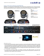
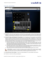
RoboSHOT HD Cameras for MATRIX PRO Diagram: Basic Wiring Configuration with MATRIX PRO RoboSHOT 12 cameras with AV Bridge Matrix PRO showing basic connectivity with color coded RJ-45 jacks. Obviously, there's a whole bunch more stuff going on here with the MATRIX PRO, that's why we suggested earlier that using the MATRIX PRO manual in conjunction with this manual for the RoboSHOT's is your best bet. RoboSHOT 12 HD PTZ Cameras Key: RS-232 Cat-5 Blue Line Bidirectional RS-232 Control Signals Orange Line EZ-POWER VIDEO Cat-5 Power to Camera and differential HD Video from the Camera Cat-5 Cable Distance for RoboSHOT video, power and control is up to 100' RS-232 Cat-5 EZ-POWER VIDEO Cat-5 RS-232 Cat-5 EZ-POWER VIDEO Cat-5 AV Bridge MATRIX PRO Rear Panel Connections Simulated Video Feed HD Video Monitor HDMI Out to Monitor PRE-INSTALLATION Choose camera mounting location, paying close attention to camera viewing angles, lighting conditions, possible line of site obstructions, and checking for in-wall obstructions where the camera is to be mounted. Always pick a mounting location that will optimize the performance of the camera. Please locate the camera to enable easy positioning of the camera body with the ability to point down and away from the ceiling and a pile of fluorescent lighting cells. Cameras generally don't like to be swamped with fluorescent light and nobody sits or stands on the ceiling anyway...as a general rule. For Power/Video and RS-232 signals, use standard Cat-5/5e/6 cable (568B termination and real RJ-45 connectors) from the EZ-POWER VIDEO and RS-232 ports on the back of the RoboSHOT to the MATRIX PRO. These jacks are color coded for ease of connection. RoboSHOT HD Cameras for MATRIX PRO - Document Number 342-1027 Rev A Page 11 of 41
-
 1
1 -
2
-
3
-
4
-
5
-
 6
6 -
 7
7 -
 8
8 -
 9
9 -
 10
10 -
 11
11 -
 12
12 -
 13
13 -
 14
14 -
 15
15 -
 16
16 -
17
-
18
-
19
-
20
-
21
-
22
-
23
-
24
-
25
-
26
-
27
-
28
-
29
-
30
-
31
-
32
-
33
-
34
-
35
-
36
-
37
-
38
-
39
-
40
-
41
 |
 |
