Vaddio AV Bridge MATRIX PRO RoboSHOT Cameras for the AV Bridge MATRIX PRO Manu - Page 12
Determine Camera Mount Location and Mount
 |
View all Vaddio AV Bridge MATRIX PRO manuals
Add to My Manuals
Save this manual to your list of manuals |
Page 12 highlights
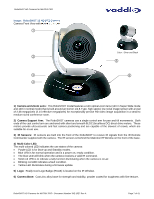
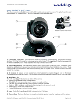
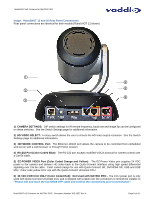
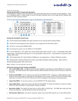
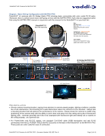
RoboSHOT HD Cameras for MATRIX PRO More Notes: Use of pass-thru type RJ-45 connectors is highly discouraged. The Vaddio Cat-5 wiring standard uses pins 1, 2, 7 and 8 on both the power/video and the control Cat-5e cables. The pass-through connectors have proven to provide insufficient connectivity for these important signals. They are OK for voice and data that use the center pins only, but not for cabling systems that use all the pins. Installation Basics: The RoboSHOT cameras include a Thin Profile Wall Mount for...wall mounting the camera. There are options for IN-Wall™ mounts and IN-Ceiling™ Half-Recessed as well. The Cat-5 cabling ideology is especially convenient for camera mounting when the camera location is not anywhere near an AC outlet. Installation is simplified in that no custom 8-Pin mini-din cables or expensive plenum coax cables or multi-pin cables or power outlets are required near the camera location. All Cat-5 cabling is routed to the head-end using with standard straight through RJ-45 connectors (568B termination). "Pass-thru" type RJ-45 connectors should be avoided, like a bad cliché. Determine Camera Mount Location and Mount After determining the optimum location of the camera system, route the required Cat-5e cables from the camera to the head-end Quick-Connect. Test and mark the Cat-5e cables: EZ-POWER VIDEO and RS-232. The Cat-5e cables should feed-through the cable management slots provided by all Vaddio mounting options. If the wall mount is to be mounted on a 2-gang wall box, use the screws supplied with the wall box cover plate to attach the Thin Profile Wall Mount Bracket. If mounting to drywall with wall anchors, use the four (4) quality wall anchors and screws provided. Use a level to level the mount... The mounting holes are slotted and are 90° opposing to provide easy leveling. Level the mount and place the camera on the mount. Connect the marked and tested Cat-5e cables to the appropriate RJ-45 jacks. Check the level again to avoid any of those weird Batman camera angles. Use the provided ¼"-20 x .375 mounting screw to attach the Camera to the mount. System Wiring Follow the sample wiring diagram (page 11) for connecting the Cat-5e cables to the camera and Quick-Connect Interface. Additional diagrams are available on the Vaddio website. Connect the RoboSHOT camera side as follows: Connect the EZ-POWER VIDEO Cat-5 to the EZ-POWER VIDEO RJ-45 connector on the RoboSHOT. Connect the RS-232 control Cat-5 to the RS-232 RJ-45 on the RoboSHOT. Connect the MATRIX PRO side as follows: Connect the RS-232 Cat-5 cable to the RS-232 connector on the MATRIX PRO. Connect the EZ-POWER VIDEO Cat-5e to the EZ-POWER VIDEO RJ-45 connector on the MATRIX PRO. Note: Please check all Cat-5 cables for continuity in advance of final connection (568B). Plugging the EZ-POWER/VIDEO Cat-5 cable into the wrong RJ-45 or using the wrong pin-out may cause damage to the camera system and void the warranty! Power Up Connect the power supply provided with the MATRIX PRO and Plug the AC side into an AC outlet (thanks Captain Obvious). Power will travel down the EZ-POWER VIDEO Cat. 5 cable to the camera. The camera will boot up and in a few seconds and initialize the pan/tilt motors. The MATRIX PRO will auto-identify the camera and load the specific control protocols for the camera, HSDS (differential) video will travel back down the Cat-5 cable and be ready to accept control information from MATRIX PRO. RoboSHOT HD Cameras for MATRIX PRO - Document Number 342-1027 Rev A Page 12 of 41
-
 1
1 -
2
-
3
-
4
-
5
-
6
-
 7
7 -
 8
8 -
 9
9 -
 10
10 -
 11
11 -
 12
12 -
 13
13 -
 14
14 -
 15
15 -
 16
16 -
 17
17 -
18
-
19
-
20
-
21
-
22
-
23
-
24
-
25
-
26
-
27
-
28
-
29
-
30
-
31
-
32
-
33
-
34
-
35
-
36
-
37
-
38
-
39
-
40
-
41
 |
 |
