Vaddio AV Bridge MATRIX PRO RoboSHOT Cameras for the AV Bridge MATRIX PRO Manu - Page 9
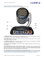
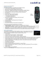
Image, RoboSHOT 12 and 30 Rear Panel Connections
 |
View all Vaddio AV Bridge MATRIX PRO manuals
Add to My Manuals
Save this manual to your list of manuals |
Page 9 highlights
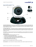
RoboSHOT HD Cameras for MATRIX PRO Image: RoboSHOT 12 and 30 Rear Panel Connections Rear panel connections are identical for both models (RoboSHOT 12 shown). ① ④ ② ⑤ ⑥ ③ 1) CAMERA SETTINGS: DIP switch settings for IR remote frequency, baud rate and image flip can be configured on these switches. See the Switch Settings page for additional information. 2) HD VIDEO SELECT: A rotary switch allows the user to choose the HD video output resolution. See the Switch Settings page for additional information. 3) NETWORK CONTROL Port: The Ethernet 10/100 port allows the camera to be controlled from embedded web server with a web browser or through Telnet session. 4) RS-232 Port (Color Coded Blue): The RS-232 port accepts modified VISCA protocol for camera control over a Cat-5e cable. 5) EZ-POWER VIDEO Port (Color Coded Orange and Yellow): The EZ-Power Video port supplies 24 VDC power to the camera and delivers HD video back to the Quick-Connect interface using high speed differential signaling over Cat-5e cable. Color coded orange for use with Quick-Connect SR, DVI/HDMI-SR, USB and USB Mini. Color code yellow is for use with the Quick-Connect Universal CCU. 6) 36 VDC FOR CCU ONLY (Color Coded Red): Not Used with MATRIX PRO - The CCU power port is only used with Quick-Connect Universal CCU and is shipped with a label over the connectors to remind the installer to "Please test and mark the Cat-5/5e/6 UTP cable and confirm the connectivity prior to termination". RoboSHOT HD Cameras for MATRIX PRO - Document Number 342-1027 Rev A Page 9 of 41
-
 1
1 -
2
-
3
-
 4
4 -
 5
5 -
 6
6 -
 7
7 -
 8
8 -
 9
9 -
 10
10 -
 11
11 -
 12
12 -
 13
13 -
 14
14 -
15
-
16
-
17
-
18
-
19
-
20
-
21
-
22
-
23
-
24
-
25
-
26
-
27
-
28
-
29
-
30
-
31
-
32
-
33
-
34
-
35
-
36
-
37
-
38
-
39
-
40
-
41
 |
 |
