ViewSonic PJ750 Service Manual - Page 17
ViewSonic PJ750 Manual
 |
View all ViewSonic PJ750 manuals
Add to My Manuals
Save this manual to your list of manuals |
Page 17 highlights
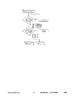
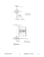
the RGB signal is input Check at operating mode Are signal input at each pin of NO E101 on the PWB ass'y Main? PWB ass'y Signal YES C),0 : (TP1R) : R signal (4),© : (TP1G) : G signal (7),(0) : (TP1B) : B signal 0,6 : (TP1H) : H sync 0,0 : (TP1V) : V sync Are voltage input at pins '2) , ,C) ,0') of NO E800 on the PWB Power unit (circuit) ass'y Main? (2) (TP46): +14V YES (TP47): +17V 0C) (TP48): +6V (TP49): +4.3V PWB ass'y Main LCD Panel ViewSonic Corporation 14 CONFIDENTIAL -- DO NOT COPY PJ750
-
 1
1 -
2
-
3
-
4
-
5
-
6
-
7
-
8
-
9
-
10
-
11
-
 12
12 -
 13
13 -
 14
14 -
 15
15 -
 16
16 -
 17
17 -
 18
18 -
 19
19 -
 20
20 -
 21
21 -
 22
22 -
23
-
24
-
25
-
26
-
27
-
28
-
29
-
30
-
31
-
32
-
33
-
34
-
35
-
36
-
37
-
38
-
39
-
40
-
41
-
42
-
43
-
44
-
45
-
46
-
47
-
48
-
49
-
50
-
51
-
52
-
53
-
54
-
55
 |
 |

the
RGB
signal
is
input
Check
at
operating
mode
Are
signal
input
at
each
pin
of
E101
on
the
PWB
ass'y
Main?
NO
PWB
ass'y
Signal
YES
C),0
:
(TP1R)
:
R
signal
(4),©
:
(TP1G)
:
G
signal
(7),(0)
:
(TP1B)
:
B
signal
0,6
:
(TP1H)
:
H
sync
0,0
:
(TP1V)
:
V
sync
Are
voltage
input
at
pins
'2)
of
NO
Power
unit
,
,C)
,0')
E800
on
the
PWB
(circuit)
ass'y
Main?
(2)
(TP46):
+14V
YES
(TP47):
+17V
C)
(TP48):
+6V
0
(TP49):
+4.3V
PWB
ass'y
Main
LCD
Panel
ViewSonic
Corporation
14
CONFIDENTIAL
--
DO
NOT
COPY
PJ750