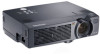
ViewSonic PJ750 Service Manual - Page 29
ass'y
 |
View all ViewSonic PJ750 manuals
Add to My Manuals
Save this manual to your list of manuals |
Page 29 highlights
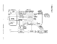
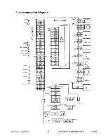
uoneiodioo oluosmam (1) Push in CNPOW,CNBAR and CNTH between the Foot folder and Styling not put in rib when Power unit. (2) You may insert which connector of E803 and E807. Cross the CNPOW and these lead. These lead and not styling near the front bezel assembling. (1) Let CNPOW pass through under the rib. (2) Engage CNTH with a claw CNPOW To PWB ass'y of Power unit (circuit) holder. Power (circuit) To PWB ass'y Rib ie' To PWB ass'y /Main CNTH projection lens side. CNPOW, CNBAR and CNTH Position of rib of front bezel Position of rib of front bezel Sensor PWB ass'y To Speaker (L) Remote control v PWB ass'y To Speaker (R) Sensor -1CNTH E803 E807 1 : r : E302 En901 CNRM CN2 ESPL E803 E302 E806 (Panel B) (Lamp)./4 4,---(CNPOW E950 a ESPR Insert E800 and E808 before PWB ass'y Main fixing because the Optical unit side of PWB ass'y Main. ri (Panel R E800 I i Sirocco fan To Sirocco fan, Lamp E800 rn E808 • I 'Panel e Sirocco fan Panel B. E808 CNBAR) To Sirocco fan, Lamp and Panel B. AdO3 ION O0 --1V11N90HNO3 P502 P702 Exhaust fan You may insert which connector of E801 and E802 for Sirocco fan. E802(panel G) E801(panel R) P602 E804 PWB ass'y Main E809 101 Position of Operation panel NG OK (CNLC) E941 PWB ass'y sensor Fix CNLC with tape on 1101, so that CNLC cannot lay on the Operation panel. Upper view (Attached PWB ass'y Main) Fix the leads from DC fan (Exhaust) and the Temperature sensor through the recess of DC fan (Exhaust) and with tape so that the wire doesn't folat. Avoide to catch the leads between the PWB ass'y Main and the Optics unit.
-
 1
1 -
2
-
3
-
4
-
5
-
6
-
7
-
8
-
9
-
10
-
11
-
12
-
13
-
14
-
15
-
16
-
17
-
18
-
19
-
20
-
21
-
22
-
23
-
 24
24 -
 25
25 -
 26
26 -
 27
27 -
 28
28 -
 29
29 -
 30
30 -
 31
31 -
 32
32 -
 33
33 -
 34
34 -
35
-
36
-
37
-
38
-
39
-
40
-
41
-
42
-
43
-
44
-
45
-
46
-
47
-
48
-
49
-
50
-
51
-
52
-
53
-
54
-
55
 |
 |
