ViewSonic PJ750 Service Manual - Page 28
Upper, Removed, ass'y
 |
View all ViewSonic PJ750 manuals
Add to My Manuals
Save this manual to your list of manuals |
Page 28 highlights
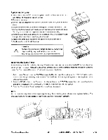
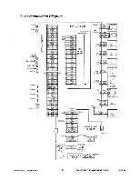
uogemdmo o!uostAam (TAPE Folding part of the lead fixed not to pass under the PWB ass'y Main. Folding part Ballast cover PWB ass'y Main To PWB ass'y Main E803,E807 A FOOT HOLDER Ballast cover Panel R Sirocco fan• r Pane B To Power unit (circuit) CN104 Hook the lead of Power unit (Ballast) at the claw. Sirocco fan Do not put the lead on the tri I ti '1 ler• ••LCN1 Trans I transformer of Power unit. I 11 'Panel G I t Sirocco far) r _ i Cla To Power unit (Ballast) Route the Sirocco fan lead through SirLoaccmopfan the opening. CN101 (Exhaust fan Route the Temperature switch Route the Sirocco fan lead through Duct plate (Lead of Power unit (Ballast) lead through the opening in the Ballast cover the inside of Duct plate. To PWB ass'y Main Cemperature switch (Lamp lead E801,E802 AdO3 ION oa -- 1VIINBCIIANO3 Route the earth lead of Optical unit through the inside of Duct plate and Optical unit. (PAS1 With the purse lock, Clamp the Ballast lead and Sirocco fan lead through the Ballast cover. Upper view (Removed PWB ass'y Main) 0 Insert a CN101 before the Optical unit installation. Route the Temperature switch lead through the opening in the Exhaust fan.
-
 1
1 -
2
-
3
-
4
-
5
-
6
-
7
-
8
-
9
-
10
-
11
-
12
-
13
-
14
-
15
-
16
-
17
-
18
-
19
-
20
-
21
-
22
-
 23
23 -
 24
24 -
 25
25 -
 26
26 -
 27
27 -
 28
28 -
 29
29 -
 30
30 -
 31
31 -
 32
32 -
 33
33 -
34
-
35
-
36
-
37
-
38
-
39
-
40
-
41
-
42
-
43
-
44
-
45
-
46
-
47
-
48
-
49
-
50
-
51
-
52
-
53
-
54
-
55
 |
 |
