ViewSonic VT2430 User Guide - Page 20
Rear View of the Product - m tv to pc
 |
UPC - 766907329711
View all ViewSonic VT2430 manuals
Add to My Manuals
Save this manual to your list of manuals |
Page 20 highlights
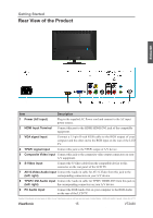
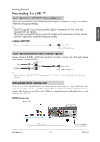
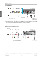
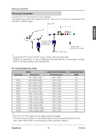
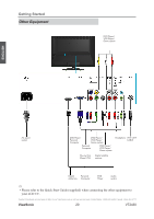
Getting Started Rear View of the Product ENGLISH Item 1 Power (AC input) Description Plug-in the supplied AC Power cord and connect to the AC input power source. 2 HDMI Input Terminal Connect this port to the HDMI/HDMI-DVI jack of the compatible equipment. 3 VGA signal input Connect a 15-pin D-sub RGB cable to the RGB output of your computer and the other end to the RGB input on the rear of the LCD TV. 4 YPbPr signal input Connect this jack to the YPbPr output of A/V device. 5 Composite Video input Connect this jack to the composite video output connectors on your A/V equipment. 6 S-Video input Connect the S-Video cable from the compatible device to this connector on the rear panel of the LCD TV. 7 AV/ S-Video Audio input Connect the Audio in cable for AV/ S-Video from this jack to the (left/ right) corresponding connectors on your A/V device. 8 YPbPr/ DVI Audio input Connect the Audio in cable for YPbPr/ HDMI-DVI from this jack to (left/ right) the corresponding connectors on your A/V device. 9 PC Audio input Connect the RGB Audio Out on your computer to the RGB Audio on the rear of the LCD TV. Contact ViewSonic service team at: http://www.ViewSonic.com or call our service team: United States 1-800-688-6688, Canada 1-866-463-4775 ViewSonic 15 VT2430
-
 1
1 -
2
-
3
-
4
-
5
-
6
-
7
-
8
-
9
-
10
-
11
-
12
-
13
-
14
-
 15
15 -
 16
16 -
 17
17 -
 18
18 -
 19
19 -
 20
20 -
 21
21 -
 22
22 -
 23
23 -
 24
24 -
 25
25 -
26
-
27
-
28
-
29
-
30
-
31
-
32
-
33
-
34
-
35
-
36
-
37
-
38
-
39
-
40
-
41
-
42
-
43
-
44
-
45
-
46
-
47
 |
 |
