ViewSonic VX500 Service Manual - Page 18
DDC2B
 |
View all ViewSonic VX500 manuals
Add to My Manuals
Save this manual to your list of manuals |
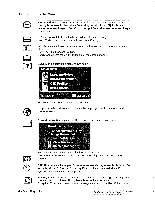
Page 18 highlights
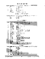
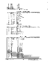
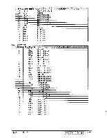
CONB8 Inverter Connector Pin # 1 2 3 4 5 6 7 Signal Name VCC VCC GND GND PENBKL GND BR_CTRL Function +12 V power supply +12 V power supply GROUND GROUND Penal Backlight On/Off control GROUND Dimming (Brightness) Control CONB5: DC Power Connector Pin # 1 2 3 Signal Name VCC GND GND +12 V power supply GROUND GROUND Function CND1: DVI Connector Pin No. 1 2 3 4 5 6 7 8 9 10 11 12 13 14 15 16 17 18 19 20 21 22 23 24 Signal Name DATAZ DATA2+ DATA2/4 SHLD Reserved 4 Reserved 5 DDC-CLK DDC-DATA Reserved 8 DATA 1DATA 1+ DATA1/3 SHLD Reserved 12 Reserved 13 DVI VCC GND DVI DET DATA 0DATA 0+ DATA0/5 SHLD DATA 5DATA 5+ CLK SHLD CLK + CLK - Description TMDS negative differential input, channel 2 TMDS positive differential input, channel 2 Logic Ground Reserved. No connection Reserved. No connection DDC2B Clock DDC2B Data Reserved. No connection TMDS negative differential input, channel 1 TMDS positive differential input, channel 1 Logic Ground Reserved. No connection Reserved. No connection + 5.0 V Power Logic Ground SENSE Pin, Pull High TMDS negative differential input, channel 0 TMDS positive differential input, channel 0 Logic Ground Reserved. No connection Reserved. No connection Logic Ground TMDS positive differential input, reference clock TMDS negative differential input, reference clock Pin # 1 2 3 4 5 6 7 8 9 Signal Name RIN GIN BIN GND GND RRET GRET BRET DCCVCCC P6: D-SUB Red Video Green Video Blue Video Ground Ground Red Video Ground Green Video Ground Blue Video Ground DDCVCC Function ViewSonic Corporation 15 Confidential - Do Not Copy VX500-1
-
 1
1 -
2
-
3
-
4
-
5
-
6
-
7
-
8
-
9
-
10
-
11
-
12
-
 13
13 -
 14
14 -
 15
15 -
 16
16 -
 17
17 -
 18
18 -
 19
19 -
 20
20 -
 21
21 -
 22
22 -
 23
23 -
24
-
25
-
26
-
27
-
28
-
29
-
30
-
31
-
32
-
33
-
34
-
35
-
36
-
37
-
38
-
39
-
40
-
41
-
42
-
43
-
44
-
45
-
46
-
47
-
48
-
49
 |
 |
