ViewSonic VX500 Service Manual - Page 7
Specifications
 |
View all ViewSonic VX500 manuals
Add to My Manuals
Save this manual to your list of manuals |
Page 7 highlights
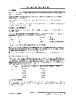
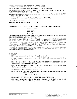
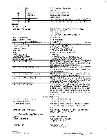
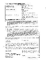
3. SPECIFICATIONS SCOPE Introduction Product Configuration This specification defines the configuration and performance requirements for the following monitors: Worldwide product Product Name: VX500 Model Number: VLCDS22825 -1 Panel: CMO M150X2 - T03 ** - 1st "*" is designated series from 0-9, 2 nd "*" is designated for region A-Z, 3RD "*" refers to color or new technology Product Definition Top Level Assembly 1. VX500 Product Assembly 2. US Power Cable. Black Notes: a. All Power cables connect into Power Supply. b. All quantities are n=1 unless otherwise specified. c. All Items go into 'All' versions (-M/-E/-P) unless otherwise specified. 3. Euro Power Cable, "Schuko". Black. 4. AC/DC Adapter. Black. 5. Analog VGA Cable. Black with PC99. connectors. HPD & DDC Compliant. 6. DVI-D Cable. Black w PC99 Connectors. 7. Audio cable. Black with PC99 Connectors. 8. Microphone cable. Black w PC99 Connectors. 9. ViewSonic System Wizard CD-ROM. 10. Multi Language Quick Start Guide. Product Assembly 1. VX500 unit with attached base and neck Mass Production Release Mass Production Approval Mass Production shall not begin until ViewSonic has issued a Mass Production Release. Component Approvals All exterior plastic components, screen printed components, labels, shipping cartons, protective foam, and printed materials require approval by ViewSonic prior to Mass Production Release. Change Control ECR/ECN All Engineering changes to the product, configuration, and software shall be approved in writing via ECR/ECN process by ViewSonic prior to implementation unless emergency case. Service Documentation / Service Manual Bills of Material, Schematics, Service Manual, and Assembly Drawings shall be provided in compliance with ViewSonic Specification VSCSPCSMVRG1.2, Service Manual, Vendor Requirements Guide. GENERAL REQUIREMENTS General Specifications Test Resolution & Frequency 1024 x 768 @ 60Hz Test Image Size Full Size Contrast and Brightness Controls Factory Default: Contrast = 50%(center), Brightness = 100% SIGNAL INTERFACE Video Interface Analog Input Connector DB-15 (Analog) Digital Input Connector DVI-D (Digital) ViewSonic Corporation 4 Confidential - Do Not Copy VX500-1
-
 1
1 -
 2
2 -
 3
3 -
 4
4 -
 5
5 -
 6
6 -
 7
7 -
 8
8 -
 9
9 -
 10
10 -
 11
11 -
 12
12 -
13
-
14
-
15
-
16
-
17
-
18
-
19
-
20
-
21
-
22
-
23
-
24
-
25
-
26
-
27
-
28
-
29
-
30
-
31
-
32
-
33
-
34
-
35
-
36
-
37
-
38
-
39
-
40
-
41
-
42
-
43
-
44
-
45
-
46
-
47
-
48
-
49
 |
 |
