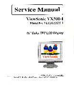
ViewSonic VX500 Service Manual - Page 6
Feature, Engineering, Specifications, Circuit, Descriptions, Troubleshooting, Theory, Operation,
 |
View all ViewSonic VX500 manuals
Add to My Manuals
Save this manual to your list of manuals |
Page 6 highlights
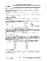
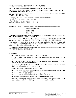
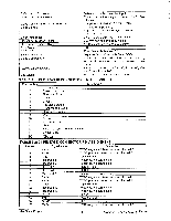
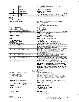
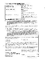
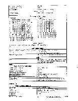
2. FEATURE The purpose of this manual provides integral information you need to maintain the LCD Monitor. And this manual is applied to the mode of 1024x768 pixels color TFT LCD Monitor. This manual is for the experienced electronic technicians and those with similar backgrounds. Send the products back to the local distributor or repair center. Do not attempt any disassembling actions that are complex or aren't mentioned in the troubleshooting section. The manual includes Engineering Specification, Front Panel Control description, Circuit Description, Troubleshooting, Theory of Operation, Mechanical Assembly, Service Parts List, and Circuit Diagram. Each section will be briefly discussed below. ENGINEERING SPECIFICATIONS This SECTION provides the engineering specification for the designated LCD monitor. Since we only provide a reference engineering specification in this service manual, Please refer to Document # VSCEPRSPEC1496,ViewSonie Engineering Product Specification for detailed product specification. CIRCUIT DESCRIPTIONS The first part of this SECTION provides a functional block diagram for the LCD Monitor. The second part of this SECTION consists of a detailed I/O connector PIN ASSIGNMENT for the PCBs. TROUBLESHOOTING Maintenance procedures described in this section are intended to isolate faulty parts and replace them in the field. The section makes explanations on how to detect errors, through a series of sequential flow chart for fault detection and means of corrections. The material contained in this section provides basic troubleshooting techniques on the module level. THEORY OF OPERATION This section is written and designed for use on in-lab troubleshooting. The section contains the detailed description on the operations of parts, which are labelled on the Functional Block Diagram. The section is intended for in-lab repair personnel who would conduct an in-lab troubleshooting of the system. MECHANICAL ASSEMBLY This section contains an Exploded Drawing for the system, for which can be used by the repair personnel for parts identity. SERVICE PARTS LIST This section aims to serve as a guide in procuring replacement parts for this product. ViewSonic Corporation 3 Confidential - Do Not Copy vx500-1
-
 1
1 -
 2
2 -
 3
3 -
 4
4 -
 5
5 -
 6
6 -
 7
7 -
 8
8 -
 9
9 -
 10
10 -
 11
11 -
 12
12 -
13
-
14
-
15
-
16
-
17
-
18
-
19
-
20
-
21
-
22
-
23
-
24
-
25
-
26
-
27
-
28
-
29
-
30
-
31
-
32
-
33
-
34
-
35
-
36
-
37
-
38
-
39
-
40
-
41
-
42
-
43
-
44
-
45
-
46
-
47
-
48
-
49
 |
 |
