Viking RVER3301 Installation Instructions
Viking RVER3301 Manual
 |
View all Viking RVER3301 manuals
Add to My Manuals
Save this manual to your list of manuals |
Viking RVER3301 manual content summary:
- Viking RVER3301 | Installation Instructions - Page 1
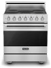
Installation 3 Series Freestanding 30" Electric Self-Clean Range RVER3301 / CRVER3301 - Viking RVER3301 | Installation Instructions - Page 2
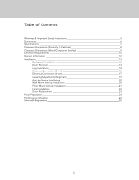
Table of Contents Warnings & Important Safety Instructions 3 Dimensions 6 Specifications 7 Clearance Dimensions (Proximity to Cabinets 8 Clearance Dimensions (Wood/Composite Overlay Installation 22 Door Replacement 23 Final Preparation 24 Performance Checklist 24 Service & Registration 25 2 - Viking RVER3301 | Installation Instructions - Page 3
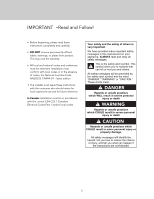
.1/NFPA-54 - latest edition. • The installer must leave these instructions with the consumer who should retain for local inspector's use and others is very important. We have provided many important safety messages in this manual and on your appliance. ALWAYS read and obey all safety messages. This - Viking RVER3301 | Installation Instructions - Page 4
use of a GFI is normally related to the location of a receptacle with respect to any significant sources of water or moisture. • Viking Range, LLC will NOT warranty any problems resulting from GFI outlets which are not installed properly or do not meet the requirements below. If the use of a GFI is - Viking RVER3301 | Installation Instructions - Page 5
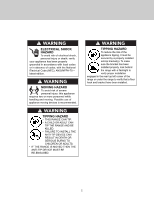
WARNING ELECTRICAL SHOCK HAZARD To avoid risk of electrical shock, personal injury or death; verify your appliance has been properly grounded in accordance with local codes or in absence of codes, with the National Electrical Code (NEC). ANSI/NFPA-70 - latest edition. WARNING MOVING HAZARD To avoid - Viking RVER3301 | Installation Instructions - Page 6
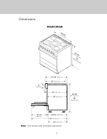
Dimensions RVER/CRVER (2795-.97/c8m") ((99413..0153c-ct7m7mo/"))8mm"ainx.. 6" (15.2 cm) 27-1/8" (68.9 cm) 25" (63.5 cm) 29" (73.7 cm) 25" (63.5 cm) 35-7/8" (91.1 cm) min. to 37" (94 cm) max. 19-1/4" (48.9 cm) 25-3/4" (65.4 cm) 45" (114.3 cm) 24" (61.0 cm) Note: Unit shown with standard - Viking RVER3301 | Installation Instructions - Page 7
Specifications Description Overall width Overall height Overall depth from rear Additions to base height Electrical requirements Maximum wattage/amp usage Surface element rating Left front Left rear Center Right front Right rear Oven interior width Oven interior height Oven interior depth Oven - Viking RVER3301 | Installation Instructions - Page 8
Clearance Dimensions (Proximity to Cabinets) • This range may be installed directly adjacent to existing 36" (91.4 cm) high base cabinets. IMPORTANT: The side trim MUST be 3/8" (.95 cm) above the adjacent base cabinet countertop. This can be accomplished by raising the unit using the adjustment - Viking RVER3301 | Installation Instructions - Page 9
hood being WoodO/Cveormlapyosite 66" (167.6 cm) to 72" (182.9 cm) above the floor. Refer to the range hood installation instructions for additional information. These dimensions provide for safe and efficient operation of the hood. ((7611268672""t..mmo69 accinmmx..)) WoodO/Cveormlapyosite - Viking RVER3301 | Installation Instructions - Page 10
use of a GFI is normally related to the location of a receptacle with respect to any significant sources of water or moisture. Viking Range, LLC will NOT warranty any problems resulting from GFI outlets which are not installed properly or do not meet the requirements below. If the use of a GFI is - Viking RVER3301 | Installation Instructions - Page 11
Electrical Requirements Electric access area 3-1/2" (8.9 cm) 3" (7.6 cm) SIDE VIEW 6" (15.2 cm) 6" (15.2 cm) 4-3/8" (11.1 cm) REAR VIEW 11 - Viking RVER3301 | Installation Instructions - Page 12
. If you notice the cooling fan is not operating or you observe unusual or excessive noise coming from the cooling fan, contact a Viking Authorized Service Center before continuing operation. Failure to do so can result in damage to the oven or surrounding cabinets. Moving, Handling, and Unpacking - Viking RVER3301 | Installation Instructions - Page 13
Installation CAUTION To avoid risk of personal injury or product damages, DO NOT use the handle or oven door to lift the oven. Remove door before installation to ensure that it is not used to lift the unit. DO NOT lift or carry the door by the handle. Removing the door must be done by your dealer, - Viking RVER3301 | Installation Instructions - Page 14
Leg Installation 1 2 Legs are packed in styrofoam top pack. Note: Legs should be installed near to where appliance is to be used, as they are not secure for long transit. 3 1 1 3 2 Note: It is strongly recommended that a pallet or lift jack be used rather than tilting. Raise unit about a - Viking RVER3301 | Installation Instructions - Page 15
Electrical Connection (3-wire) Note: If you have a 4-wire connection, see following section for 4-wire connection instructions. WARNING ELECTRICAL SHOCK HAZARD To avoid risk or electrical shock, personal injury or death; grounding product to the frame of the unit may or may - Viking RVER3301 | Installation Instructions - Page 16
Electrical Connection (3-wire) (cont.) Bare Wire Connection Eyelet Connection 4 1 1 To make a bare wire connection, use holes on the left side of the terminal block. To connect eyelet style wires, use holes on right side of terminal. 5 1 1 2 Attach line #1 (black) and line #2 (red) leads to - Viking RVER3301 | Installation Instructions - Page 17
Electrical Connection (4-wire) WARNING ELECTRICAL SHOCK HAZARD To avoid risk or electrical shock, personal injury or death; grounding product to the frame of the unit may or may not be permitted through your local codes. If ground to the frame is not permitted then a 4-conductor power cord must be - Viking RVER3301 | Installation Instructions - Page 18
Electrical Connection (4-wire) (cont.) Bare Wire Connection Eyelet Connection 4 1 1 To make a bare wire connection, use holes on the left side of the terminal block. To connect eyelet style wires, use holes on right side of terminal. 5 Feed supply cord up through hole in bottom of range back - Viking RVER3301 | Installation Instructions - Page 19
Leveling/Adjustments/Alignment 1 2 Measure the four corners in cutout area to verify if flooring is level. 3 For uneven or sloped floors, level unit with metal shims only, as the adjustment required may exceed the thread available in the leg. 4 Move unit into opening. 5 (03.9/58"cm) Check that - Viking RVER3301 | Installation Instructions - Page 20
Leveling/Adjustments/Alignment (cont.) 7 Set the high corner of range so that the top of side trim is 3/8" (0.95 cm) above countertop. Level range to high corner. Anti-tip Device Installation WARNING TIPPING HAZARD • THIS RANGE CAN TIP. • A CHILD OR ADULT CAN TIP THE RANGE AND BE KILLED. • FAILURE - Viking RVER3301 | Installation Instructions - Page 21
Wall Mount Anti-tip Installation 1 2 (A) 3(9-.52/c8m") +1/2"(A(1).3 cm) Measure from floor to bottom of the anit-tip opening located on the back of range. This will be measurement (A). Locate anti-tip bracket on rear wall with the top left corner at measurement (A) plus 1/2" (1.3 cm) from the - Viking RVER3301 | Installation Instructions - Page 22
Floor Mount Anti-tip Installation Dim A from Rear Wall 3-7/8" WIthout Standoffs (9.8 cm) Dim A from Rear Wall 4-5/8" WIth Standoffs (11.7 cm) 1 A (2810-1.69/24cm" ) 2 1 1 Ø(.321/c8m") Refer to chart for dimension A based on whether or not standoffs are used with the rear trim device. Mark - Viking RVER3301 | Installation Instructions - Page 23
Final Installation 1 2 Connect electrical in shaded area. See the "Electrical Requirements" section for more information. 3 Slide range into place. Be sure anti-tip bracket slides into the anit-tip opening. (03.9/58"cm) Check that unit is level side to side and front to back. The side trim must - Viking RVER3301 | Installation Instructions - Page 24
Door Replacement 1 2 Carefully realign door on hinges. Slide in and down. 3 Open door completely. Fold latches forward until locked in place. Close door 24 - Viking RVER3301 | Installation Instructions - Page 25
Final Preparation • All stainless steel body parts should be wiped with hot, soapy water and with a liquid cleaner designed for this material. If buildup occurs, DO NOT use steel wool, abrasive cloths, cleansers, or powders! If it is necessary to scrape stainless steel Performance Checklist to - Viking RVER3301 | Installation Instructions - Page 26
under the control panel. Record the following information indicated below. You will need it if service is ever required. Model number Serial number Date of purchase Date installed Dealer's name Address These installation instructions should remain with the unit for future reference. 26 - Viking RVER3301 | Installation Instructions - Page 27
27 - Viking RVER3301 | Installation Instructions - Page 28
Viking Range, LLC 111 Front Street Greenwood, Mississippi 38930 USA (662) 455-1200 For product information, call 1-888-845-4641 or visit our website at vikingrange.com F21193C EN UL C UL (093018)
-
 1
1 -
 2
2 -
 3
3 -
 4
4 -
 5
5 -
 6
6 -
 7
7 -
8
-
9
-
10
-
11
-
12
-
13
-
14
-
15
-
16
-
17
-
18
-
19
-
20
-
21
-
22
-
23
-
24
-
25
-
26
-
27
-
28
 |
 |
Installation
3 Series
Freestanding 30” Electric Self-Clean Range
RVER3301 / CRVER3301