Viking VGIC2454BSS Installation Instructions - Page 10
INITIAL IGNITION OF BURNERS For Open Surface Burners
 |
View all Viking VGIC2454BSS manuals
Add to My Manuals
Save this manual to your list of manuals |
Page 10 highlights
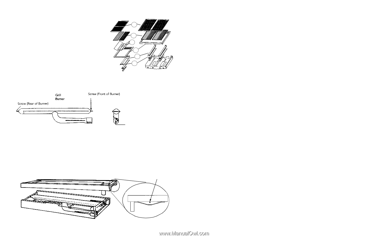
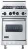
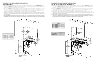
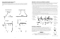
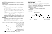
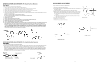
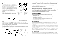
GRILL/GRIDDLE BURNER ADJUSTMENT 12" Grill Assembly 24" Grill Assembly Grill 1. The grill burner orifice and air shutter are located beneath the front end of the grill assembly. To gain access to the adjustment, remove the grill grate, grate support, flavor generator plates, and the burner shield. 2. Remove the screw at the front and rear of the burner. 3. Lift the burner off the orifice and locate the air shutter adjustment screw at the end of the burner. 4. Loosen the screw and adjust the air shutter to the desired setting [for natural gas open shutter approximately 7/16" (1.1 cm); for LP gas open the air shutter approximately 3/8" (.95 cm)]. 5. Tighten the screw, then replace the burner on the orifice. 6. Check the flame for desired height before replacement of the above parts. 7. The flame adjustments are the same as the surface burners. Use a 1/2" (1.3 cm) deep socket to adjust the orifice head; turn clockwise to decrease flame and counter clockwise to increase flame. 1 2 3 4 5 6 1. Grill Grates 2. Flavor Generator plates 3. Heat Deflector 4. Grill Frame 5. Grill Burner Sheild (Do not remove from burner) 6. Burner (Do not remove) Air shutter adjustment screw Griddle 1. To gain access to the burner orifice and air shutter, remove grates and grate supports located on either side of the griddle. Lift and remove the griddle. CAUTION: Before fully removing the griddle assembly, lift the griddle assembly approximately 4" above the griddle box. Carefully remove the temperature probe from the probe bracket. (See Detail "B") Make note of the position of the temperature probe so it can be reinstalled properly. Failure to properly reinstall can result in damage to the temperature probe. 2. Carefully remove the ignitor and put to the side. 3. Remove the metal plate located below the burner. 4. Remove the screws at the front and rear of the burner, remove the burner tube and locate the air shutter adjustment screw at the end of the burner tube. 5. Flame adjustments are the same as the grill #4-#7. 6. Replace all griddle parts and griddle. Probe Bracket Detail B 18 INITIAL IGNITION OF BURNERS (For Open Surface Burners) All ranges are tested before leaving the factory. Field adjustments may be necessary for proper mixture of gas and air for proper operation. When the range is connected to gas and electric service, it should be adjusted by a qualified technician. When adjustments are required, contact your dealer/installer for corrections. If assistance is not available, contact Viking Range Corporation Preferred Service for the nearest authorized service agent at (662) 451-4133. All corrections to installation are the responsibility of the dealer/installer or end user. INITIAL IGNITION OF BURNERS (For Sealed Surface Burners) All sealed top ranges are tested before leaving the factory. There are no adjustments for the sealed surface burners if connected according to the information on the rating plate. Check each burner for proper operations. Flames should be blue in all settings. If service is required, contact your dealer for the name of their authorized service agency. If none is available, contact Viking Preferred Service for the nearest authorized service agency in your area. Gas conversions and initial installation are not the responsibility of the manufacturer. PERFORMANCE CHECKLIST The installer should carry out the following performance checks. Refer to instructions below. 1. Check surface burner ignition. 2. Check air shutter adjustment - sharp blue flame, no yellow tipping, sooting or flame lifting 3. Check low flame adjustment - surface burner valve center stem adjustment. 4. Check griddle ignition - all burner ports. 5. Check grill ignition - all burner ports. 6. Visually check tubular burner reignition to be sure both sides are relighting each time. 6. Check for gas leaks (odors) at all gas connections. 7. Check oven bake and convection bake function. FINAL PREPARATION 1. Some stainless steel parts may have a plastic protective wrap which must be removed. The interior of the oven should be washed thoroughly with hot, soapy water to remove film residues and any installation dust or debris before being used for food preparation, then rinsed and wiped dry. Solutions stronger than soap and water are rarely needed. 2. All stainless steel body parts should be wiped with hot, soapy water and with a liquid cleaner designed for this material. If buildup occurs, do not use steel wool, abrasive cloths, cleaners, or powders! If it is necessary to scrape stainless steel to remove encrusted materials, soak with hot, wet cloths to loosen the material, then use a wood or nylon scraper. Do not use a metal knife, spatula, or any other metal tool to scrape stainless steel! Scratches are almost impossible to remove. NOTE: These installation instructions should remain with the unit for future reference. The electrical diagram is located beneath the drip tray in the rear corner of the burner box. Remove the right rear burner bowl and pull the drip tray forward approximately 6" (15.2 cm). REPLACEMENT PARTS Only authorized replacement parts may be used in performing service on the oven. Replacement parts are available from factory authorized parts distributors. Contact Viking Range Corporation Preferred Service, (662) 451-4133, for the nearest parts distributor in your area. 19
-
 1
1 -
2
-
3
-
4
-
 5
5 -
 6
6 -
 7
7 -
 8
8 -
 9
9 -
 10
10
 |
 |