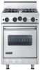
Viking VGIC2454BSS Installation Instructions - Page 5
Back Trim Accessories, Anti-tip Stability Device Installation Instructions, Ranges Equipped
 |
View all Viking VGIC2454BSS manuals
Add to My Manuals
Save this manual to your list of manuals |
Page 5 highlights
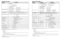
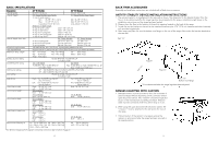
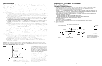
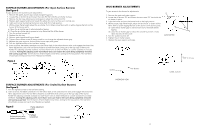
BASIC SPECIFICATIONS Description Overall width Overall height Overall depth from rear Electrical requirements Gas requirements Maximum amp usage/ Surface burner rating Griddle burner rating Grill burner rating Broil rating Bake rating Oven Interior width Oven Interior height Oven Interior depth Oven Interior overall size Approximate Shipping wt. 48" W. Models 60" W. Models 47-7/8" (121.6 cm) 59-1/2" (151.1 cm) 24" Deep Models Base Height 27" Deep Models Base Height To top of grate support - Min. 35-7/8 " (91.1 cm) to Min. 36-1/8" (91.8 cm Max. 37-5/8" (95.6 cm) Max 39-1/8" (99.4 cm) Legs adjust 1-3/4" (4.5 cm) Legs adjust 3" (7.6 cm) Additions to Base Height To top of spider grate - add 1-1/8" (2.9 cm) To top of island trim - add 1-1/4" (3.2 cm) To top of 6" backguard - add 6" (15.2 cm) To top of 10" backguard - add 10" (25.4 cm) To top of high shelf - add 23-1/2" (59.7 cm) 24" Deep Models 27" Deep Models To end of side panel - 24-15/16" (63.3 cm) 27" (68.6 cm) To end of control panel - 27-7/8" (70.8 cm) 28-3/4" (73.0 cm) To end of knobs - 28-3/8" (72.0 cm) 30-3/8" (77.2 cm) 120 VAC/60 Hz; 4 ft. (121.9 cm), 3-prong plug attached to unit Shipped natural or LP/Propane gas; convert with conversion kit (purchased separately) 6G - 16.0 amps 4Q - 12.4 amps 6G - 23.6 amps 6Q - 12.4 amps 4G - 19.6 amps 6GQ - 20.0 amps 4GQ - 16.0 amps 15,000 BTU Nat./13,500 BTU LP (4.4 kW/4.0 kW) 12" / 18" Wide 24" Wide 15,000 BTU Nat./12,500 BTU LP Two 15,000 BTU ea. Nat./12,500 BTU ea. LP (4.4 kW/3.7 kW) (Two 4.4 kW ea./3.7 kW ea.) 12" - 1@ 18,000 BTU Nat. (5.3 kW)/16,000 BTU LP (4.7 kW) 24" - 2@ 13,000 BTU Nat./LP (4.4 kW) 18,000 BTU Nat./16,000 BTU LP (5.3 kW/4.7 kW) Right - Two 15,000 BTU ea. Nat./LP Two 15,000 BTU ea. Nat./LP (Two 4.4 kW ea.) (Two 4.4 kW ea.) Left - One 15,000 BTU ea. Nat./LP Two 15,000 BTU ea. Nat./LP (One 4.4 kW ea.) (Two 4.4 kW ea.) Right - 24-1/8" (61.3 cm) Both - 24-1/8" (61.3 cm) Left - 13-3/8" (34.0 cm) 24" D. Models Both - 16-1/8" (41.0 cm) 27" D. Models 27" D. Models Both - 14-1/8" (35.9 cm) Both- 14-1/8" (35.9 cm) 24" D. Models Right - 17-5/8" (44.8 cm) Left - 18-3/4" (47.6 cm) 27" D. Models 27" D. Models Right - 19-1/4" (48.9 cm) Both - 19-1/4" (48.9 cm) Left - 21-1/4" (54.0 cm) 24" D. Models Right - 4.0 cu. ft. Left - 2.3 cu. ft 27" D. Models 27" D. Models Right - 3.8 cu. ft. Both - 3.8 cu. ft. Left - 2.3 cu. ft 6G - 591 lb. (266.0 kg) 4Q - 586 lb. (263.7 kg) 6G - 762 lb. (342.9 kg) 6Q - 586 lb. (263.7 kg) 4G - 596 lb. (268.5 kg) 6GQ - 757 lb. (340.7 kg) 4GQ - 596 lb. (268.5 kg) (For Minimum Clearances from adjacent combustible construction refer to bottom of page 4.) 8 BACK TRIM ACCESSORIES Assembly and installation instructions are included with all back trim accessories. ANTI-TIP STABILITY DEVICE INSTALLATION INSTRUCTIONS 1. The anti-tip bracket is to be attached to the rear wall as shown. The dimension for the bracket location from the floor is to be determined after the range legs have been adjusted to the proper installation height shown in the installation instructions and the range has been leveled. 2. Measure from the floor to the bottom of the anti-tip opening located on the back of the range. 3. Locate the anti-tip bracket on the wall at the measure dimension plus 1/16" (0.16 cm) clearance and attach securely with provided toggle bolts. 4. Slide range into place. Be sure the bottom rear flange on the rear of the range slides under the bracket attached to the rear wall. Item "A" Figure 1 "A" Item Figure 2 Item "B" Bottom rear flange To be determined after the range legs have been adjusted. RANGES EQUIPPED WITH CASTERS 1. Adequate means must be provided to limit the movement of castered ranges without depending on the connector and/or quick disconnect device. This "restraint" should be inspected as part of the maintenance and safety procedure. Restraint cable must be connected at all times when range is in use. 2. When using the quick disconnect device and/or casters, the "restrainer" must be attached to the wall and to the rear of the range. 3. If disconnection of the restraint is necessary, ensure the restraint is reconnected after the range has been returned to its original position. 9
-
 1
1 -
 2
2 -
 3
3 -
 4
4 -
 5
5 -
 6
6 -
 7
7 -
 8
8 -
 9
9 -
 10
10
 |
 |
