Viking VGIC2454BSS Installation Instructions - Page 7
Important: Leveling/adjustments/alignment, Electrical Connection - appliances
 |
View all Viking VGIC2454BSS manuals
Add to My Manuals
Save this manual to your list of manuals |
Page 7 highlights
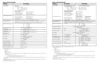
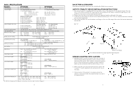
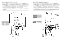
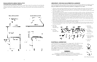
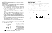
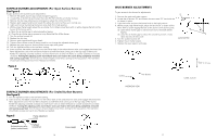
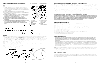
WOOD/COMPOSITE OVERLAY INSTALLATION (Including Custom Ventilator Installation) The bottom of the hood should be 30" (76.2 cm) min. to 36" (91.4 cm) above the countertop. This would typically result in the bottom of the hood being 66" (167.6 cm) to 72" (182.9 cm) above the floor. Refer to the rangehood installation instructions for additional information. These dimensions provide for safe and efficient operation of the hood. WALL INSTALLATION ISLAND INSTALLATION 12 IMPORTANT: LEVELING/ADJUSTMENTS/ALIGNMENT Careful leveling of the range is critical not only to performance, but also to allow the alignment of oven doors and drip tray. Closely follow the procedures below to ensure proper performance and appearance of the range. The range being even slightly out of level will significantly contribute to misalignment of oven doors. 1. If the floor is smooth and level, level the unit with the screw thread of the legs. Set the high corner of the range so that the top of the grate support is 3/8" (.95cm) above the countertop, and level the range to the high corner. 2. If the floor is uneven or has a decided slope, level the unit with metal shims, as the adjustment required may exceed the thread available in the leg. 3. Proper and careful leveling of the range is necessary for proper alignment of the oven doors. The body of the range does not have a rigid frame to hold it into one position. This nonrigid framework allows the range to shift with unlevel floors or slanted cabinets. Moving any one of the adjustable leveling legs up or down will shift the range body. Increasing the length of the right front leveling leg will raise the right front corner of the range, moving the top of the door to the left. Lowering the right front leveling leg will cause the tip of the door to move to the right. Using the left front leveling leg will give you the opposite effect. Raising the left front corner will move the top of the door to the right. Lowering the corner will move the top of the door to the left. The rear leveling legs will also have an effect on the door alignment. 3. After the range is properly leveled, the drip tray handle may be aligned by loosening the screws and adjusting the handle horizontally within the limits provided by the slotted screw holes. 4. A level should be placed across the top of the range and the unit leveled both front-to-back and side-to-side. If it is not level, burner combustion may be erratic, liquid, or semi-liquid batters will cook at an angle, and the unit may not function efficiently. A. Right Side Front / Back Adjustable Legs A. Right Side Front / Back Adjustable Legs B. Left Side Front / Back Adjustable Legs B. Left Side Front / Back Adjustable Legs C. Door HInge D. Spacing between edge of door and side panel ELECTRICAL CONNECTION The 24"W, 30"W., 36" W., and 48" W. units are equipped with a 120 volt/60 Hz, 16 amp plug. The 60" W. units are equipped with a nema 5-20p, 20 amp plug. (See illustrations). The minimum of 102 VAC is required for proper operation of gas ignition systems. This circuit must be grounded and properly polarized. The units are equipped with a 16-3 SJT power cord, and if an extension is required, it must be of at least this gauge. NOTE: If electrical power is not supplied or is interrupted, the oven, griddle, and the broiler will not work at all. The surface burners and grill burner will have to lit manually with a match. WARNING!! Electrical Grounding Instructions This appliance is equipped with a three prong plug for your protection against shock hazard and should be plugged directly into a properly grounded socket. DO NOT cut or remove the grounding prong from this plug. E. Center trim spacing 16 amp plug Nema 5-20p, 20 amp plug 13
-
 1
1 -
 2
2 -
 3
3 -
 4
4 -
 5
5 -
 6
6 -
 7
7 -
 8
8 -
 9
9 -
 10
10
 |
 |
