Viking VGIC2454BSS Installation Instructions - Page 8
Oven Tubular Gas Burner Adjustments, Refer To Below, Gas Connection
 |
View all Viking VGIC2454BSS manuals
Add to My Manuals
Save this manual to your list of manuals |
Page 8 highlights
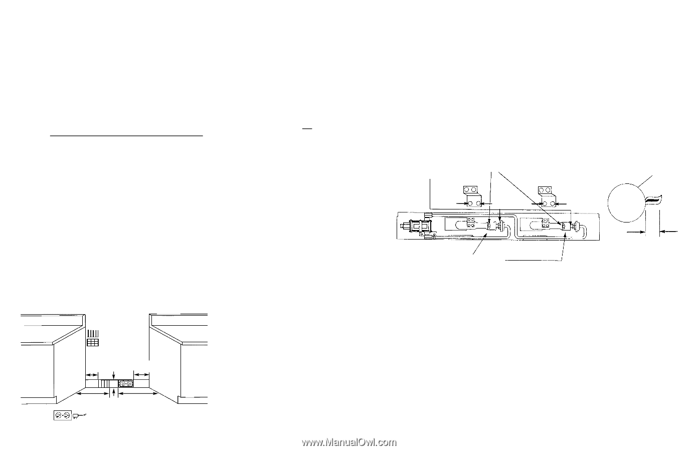
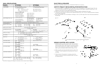
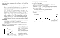
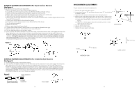
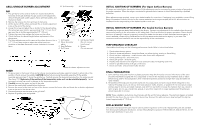
GAS CONNECTION All gas connections must be made according to national and local codes. This gas supply (service) line must be the same size or greater than the inlet line of the appliance. This range uses a 1/2" NPT (Sch 40) inlet. Sealant on all pipe joints must be resistive to LP gas. 1. Manual Shut-off Valve: This installer-supplied valve must be installed in the gas service line ahead of the appliance in the gas stream and in a position where it can be reached quickly in the event of an emergency. In Massachusetts: A "T" handle type manual gas valve must be installed in the gas supply line to this appliance. 2. Pressure Regulator a) All heavy duty, commercial type cooking equipment must have a pressure regulator on the incoming service line for safe and efficient operation, since service pressure may fluctuate with local demand. External regulators are not required on this range, because a regulator is built into each unit at the factory. Under no condition bypass this built-in regulator. b) Any conversion required must be performed by your dealer or a qualified licensed plumber or gas service company. Please provide the service person with this manual before work is started on the range. (Gas conversions are the responsibility of the dealer or end user.) c) This range can be used with Natural or LP/Propane gas. It is shipped from the factory adjusted for use with natural gas. The orifice hoods must be screwed snug when LP/Propane gas is used. (See LP/Propane conversion.) d) Manifold pressure should be checked with a manometer, natural gas requires 5.0" W.C.P. and LP/Propane requires 10.0" W.C.P. Incoming line pressure upstream from the regulator must be 1" W.C.P. higher than the manifold pressure in order to check the regulator. The regulator used on this range can withstand a maximum input pressure of 1/2 PSI (14.0" W.C.P.) If the line pressure is in excess of that amount, a stepdown regulator will be required. e) The appliance, its individual shut-off valve, and pressure regulator must be disconnected from the gas supply piping system during any pressure testing of that system at pressures in excess of 1/2 psig (3.45 kPa). f) The appliance must be isolated from the gas supply piping system by closing its individual manual shut-off valve during any pressure testing of the gas supply piping system at test pressures equal to or less than 1/2 psig (3.45 kPa). 3. Flexible Connections: a) If the unit is to be installed with flexible couplings and/or quick disconnect fittings, the installer must use a heavy-duty, AGA design-certified commercial flexible connector of at least 1/2" (1.3 cm) ID NPT (with suitable strain reliefs) in compliance with ANSI Z21.41 and Z21.69 standards. b) In Massachusetts: The unit must be installed with a 36" (3-foot) long flexible gas connector. c) In Canada: CAN 1-6.10-88 metal connectors for gas appliances and CAN 1-6.9 M79 quick disconnect device for use with gas fuel. CAUTION: Leak testing of the appliance shall be conducted according to the manufacturer's instructions. Before placing the oven into operation, always check for leaks with a soapy water solution of other acceptable method. DO NOT USE AN OPEN FLAME TO CHECK FOR LEAKS! Gas shut-off valve Electrical receptacle A properly-grounded horizontally- mounted electrical receptacle should be installed no higher than 3" (7.6 cm) above the floor, no less than 6" (15.2 cm) and no more than 12" (30.5 cm) from the right side (facing product). Check all local code requirements. 5" 3" 6" (12.7 cm) (7.6 cm) (15.2 cm) 11" (27.9 cm) 12" (30.5 cm) *NOTE: Ground plug and electrical wire toward the direction of the electrical outlet. An agency-approved, properly-sized manual shut-off valve should be installed no higher than 3" (7.6 cm) above the floor and no less than 5" (12.7 cm) and no more than 11" (27.9 cm) from the left side (facing product). To connect gas between shut-off valve and regulator, use agency-approved, properlysized flexible conduit or rigid pipe. Check all local code requirements. 14 OVEN TUBULAR GAS BURNER ADJUSTMENTS (Refer to Figure 3 below) To gain access to the oven burner adjustments: I. remove the kick plate - remove screw from each side of kick plate and tilt the top of the kick plate forward. 2. Locate the air shutter (Item #1) and loosen the set screw (Item #2) that holds the air shutter in place. 3. Light the burners by rotating the thermostat to a baking temperature. 4. Using a 1/2" (1 .3 cm) open-end wrench, adjust orifice hood (Item #3) to obtain a sharp, well defined blue inner once approximately 1/2" (1.3 cm) long. The flame should be contacting the burner at each port opening. THE FLAME SHOULD NOT EXTEND INTO THE OVEN BOTTOM VENT SLOTS. 5. With a proper flame height, adjust the air shutter (Item #1) to obtain a blue flame with no yellow tipping that contacts the burner at the burner ports. a. Open the air shutter gap (Item #1) to eliminate yellow tipping. b. Close the air shutter gap (Item #1) to prevent a noisy flame that lifts off the burner. 6. Recheck the orifice hood (Item #3) adjustment for proper gas flow. 7. Turn the thermostat off. 8. Tighten the air shutter set screw (Item #2). 9. Relight each burner and observe the flame for proper adjustments. If necessary, repeat the above. 10. Replace the kick plate. Air Shutter Set Screw (Item #2) Orifice Hood (Item #3) Burner Nat. (4) (5) L.P. Nat. (4) (5) L.P. Figure 3 Air Shutter (Item #1) 1/2" The burner flame should be 1/2" (1.3 cm) long when the air shutter is correctly adjusted. 15
-
 1
1 -
2
-
 3
3 -
 4
4 -
 5
5 -
 6
6 -
 7
7 -
 8
8 -
 9
9 -
 10
10
 |
 |