Viking VGR548 Installation Instructions
Viking VGR548 Manual
 |
View all Viking VGR548 manuals
Add to My Manuals
Save this manual to your list of manuals |
Viking VGR548 manual content summary:
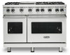
- Viking VGR548 | Installation Instructions - Page 1
Installation Professional Freestanding Ranges - Viking VGR548 | Installation Instructions - Page 2
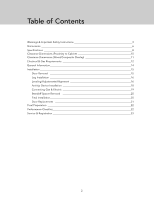
Table of Contents Warnings & Important Safety Instructions 3 Dimensions 6 Specifications 8 Clearance Dimensions (Proximity to Cabinet 10 Clearance Dimensions (Wood/Composite Final Installation 20 Door Replacement 21 Final Preparation 22 Performance Checklist 22 Service & Registration 23 2 - Viking VGR548 | Installation Instructions - Page 3
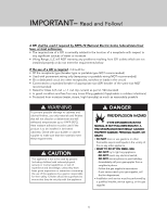
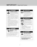
Gas Code ANSI Z223.1 INFPA54. • The installer must leave these instructions with the consumer who should retain for local inspector's use and for is very important. We have provided many important safety messages in this manual and on your appliance. ALWAYS read and obey all safety messages. This - Viking VGR548 | Installation Instructions - Page 4
or moisture. • Viking Range, LLC will NOT warranty any problems resulting from GFI IF THE INFORMATION IN THIS MANUAL IS NOT FOLLOWED EXACTLY, instructions. -If you cannot reach your gas supplier, call the fire department. • Installation and service must be performed by a qualified installer, service - Viking VGR548 | Installation Instructions - Page 5
DANGER GAS LEAK HAZARD To avoid risk of personal injury or death; leak testing of the appliance must be conducted according to the manufacturer's instructions. Before placing appliance in operation, always check for gas leaks with soapy water solution. • DO NOT USE AN OPEN FLAME TO CHECK FOR GAS - Viking VGR548 | Installation Instructions - Page 6
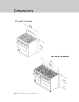
Dimensions 30" and 36" W. Models (3951-.17/c8m") 29-7/8" (75.9 cm) 1" (2.5 cm) (9(9143.15c3mc-t77mo/"m8ma"xin.).) 48" and 60" W. Models (1427(11-.756/268c.04m""c) m) Note: Unit shown with standard island trim. 6 1" (2.5 cm) (913.15c-t7mo/)8m" in. (94 37" cm) max. - Viking VGR548 | Installation Instructions - Page 7
Dimensions Side View 8-1/8" (20.6 cm) 28-1/16" (71.2 cm) 26-7/16" (67.2 cm) 1-5/8" (4.1 cm) 1" (2.5 cm) 35-7/8" (91.1 cm) min. to 37" (94.0 cm) max. 19-3/8" (49.2 cm) 25-3/4" (65.4 cm) 45-1/8" (114.6 cm) 24-5/16" (61.8 cm) Note: Unit shown with standard island trim. 7 - Viking VGR548 | Installation Instructions - Page 8
volume Overall AHAM Approximate shipping weight VGR530 VGR536 29-7/8" (75.9 cm) 35-7/8" ( accepts standard residential 1/2" (1.3 cm) ID gas service line. Unit is field convertible with proper 91.4 cm] and below) • Sides - 0" • Top grate support - 36" (91.4 cm) Above cooking surface (above 36" - Viking VGR548 | Installation Instructions - Page 9
Natural or LP/Propane, accepts standard residential 1/2" (1.3 cm) ID gas service line. Unit is field convertible with proper conversion kit Natural 5.0" W.C.P./ cooking surface (36" [91.4 cm] and below) • Sides - 0" • Top grate support - 36" (91.4 cm) Above cooking surface (above 36" [91.4 cm]) • - Viking VGR548 | Installation Instructions - Page 10
Clearance Dimensions (Proximity to Cabinets) • This range may be installed directly adjacent to existing 36" (91.4 cm) high base cabinets. IMPORTANT: The side trim MUST be 3/8" (.95 cm) above the adjacent base cabinet countertop. This can be accomplished by raising the unit using the adjustment - Viking VGR548 | Installation Instructions - Page 11
of the hood being 66" (167.6 cm) to 72" (182.9 cm) above the floor. Refer to the range hood installation instructions for additional information. These dimensions provide for safe and efficient operation of the hood. WoodO/Cveormlapyosite ((7611268672""t..mmo69 accinmmx..)) WoodO/Cveormlapyosite - Viking VGR548 | Installation Instructions - Page 12
Connection" section for grounding instructions. Must be fused seperately from any other circuit. Gas Connection The gas supply (service) line must be the the intended gas supply. Manual shut-off valve: This installer-supplied valve must be installed in the gas service line before the appliance in - Viking VGR548 | Installation Instructions - Page 13
Electrical & Gas Requirements Flexible Connections: If the unit is to be installed with flexible couplings and/or quick-disconnect fittings, the installer must use a heavy-duty AGA design-certified flexible connector of at least 1/2" (1.3 cm) ID NPT (with suitable strain reliefs) in compliance with - Viking VGR548 | Installation Instructions - Page 14
. If you notice the cooling fan is not operating or you observe unusual or excessive noise coming from the cooling fan, contact an Authorized Service Center before continuing operation. Failure to do so can result in damage to the oven or surrounding cabinets. Moving, Handling, and Unpacking Remove - Viking VGR548 | Installation Instructions - Page 15
Door Removal 1 2 step Open door completely. 3 Fold latches backward until locked in place. 4 Slowly close until latches stop door. Lift door up and out. 15 - Viking VGR548 | Installation Instructions - Page 16
Leg Installation 1 2 step step Legs are packed in cardboard top pack. Note: Legs should be installed near to where appliance is to be used, as they are not secure for long transit. 3 1 1 3 2 Note: It is strongly recommended that a pallet or lift jack be used rather than tilting. Raise unit - Viking VGR548 | Installation Instructions - Page 17
Installation 3 4 step step Move unit into opening. 5 0.95 cm Check that unit is level side to side and front to back. Side trim of the lowest corner must be 3/8" (0.95 cm) above countertop. 6 step step If leveling is required, move unit out of opening. 7 1 1 2 Lift unit and prop on wood - Viking VGR548 | Installation Instructions - Page 18
HAZARD To reduce the risk of property damage or personal injury; install anti-tipping device provided in accordance with the installation instructions in this document. Device must be engaged properly to prevent product from tipping over. Measurement (A) step 2 Y X Me+a1s/u2r"e(m1.e3nctm - Viking VGR548 | Installation Instructions - Page 19
Installation Anti-tip Device Installation (Floor Mount) 1 1-1/4" + B* A Ø(.321/c8m") Locate anti-tip bracket hook on the floor Dim A from side cabinet and 1-1/4" (3.2 cm) from rear wall when using an island trim or high shelf. If using an 8" (20.3 cm) backguard, add Dim B to the 1-1/4". Mark - Viking VGR548 | Installation Instructions - Page 20
leak testing of the appliance must be conducted according to the manufacturer's instructions. Before placing appliance in operation, always check for gas leaks with by your dealer, a qualified licensed plumber, or gas service company. Standoff Spacer Removal DANGER FIRE HAZARD Backguards come - Viking VGR548 | Installation Instructions - Page 21
. Place burner bases on top of the burner flanges and burner heads on top of the burner base. Place burner grate on top of grate support. Door Replacement 1 00..9955 ccmm Check that unit is level side to side and front to back. The side trim must be 3/8" (0.95 cm) above - Viking VGR548 | Installation Instructions - Page 22
Final Preparation • All stainless steel body parts should be wiped with hot, soapy water and with a liquid cleaner designed for this material. If buildup occurs, DO NOT use steel wool, abrasive cloths, cleansers, or powders! If it is necessary to scrape stainless steel to remove encrusted materials, - Viking VGR548 | Installation Instructions - Page 23
on the back side of the range. Record the following information indicated below. You will need it if service is ever required. Model number Serial number Date of purchase Date installed Dealer's name Address These installation instructions should remain with the unit for future reference. 23 - Viking VGR548 | Installation Instructions - Page 24
Viking Range, LLC 111 Front Street Greenwood, Mississippi 38930 USA (662) 455-1200 For product information, call 1-888-(845-4641) or visit vikingrange.com 055065-000B EN (013018)
-
 1
1 -
 2
2 -
 3
3 -
 4
4 -
 5
5 -
 6
6 -
 7
7 -
8
-
9
-
10
-
11
-
12
-
13
-
14
-
15
-
16
-
17
-
18
-
19
-
20
-
21
-
22
-
23
-
24
 |
 |
Installation
Professional Freestanding Ranges