Viper 771XV Owner Manual - Page 8
way remote diagram, standard remote configuration - 2 way remote
 |
View all Viper 771XV manuals
Add to My Manuals
Save this manual to your list of manuals |
Page 8 highlights
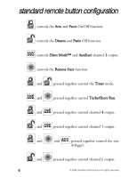
2-way remote diagram 2 3 1 4 5 6 8 7 standard remote configuration 1. Unlock/Lock Indicator (Orange) 2. Receive/Transmit Indicator (Green) 3. Remote Start/Auxiliary Indicator (Yellow) 4. Panic Indicator (Red) 5. Lock Button 6. Unlock Button 7. Remote Start Button 8. Auxiliary Channel Button © 2005 directed electronics-all rights reserved 5
-
 1
1 -
2
-
 3
3 -
 4
4 -
 5
5 -
 6
6 -
 7
7 -
 8
8 -
 9
9 -
 10
10 -
 11
11 -
 12
12 -
 13
13 -
14
-
15
-
16
-
17
-
18
-
19
-
20
-
21
-
22
-
23
-
24
-
25
-
26
-
27
-
28
-
29
-
30
-
31
-
32
-
33
-
34
-
35
-
36
-
37
-
38
-
39
-
40
-
41
-
42
-
43
-
44
-
45
-
46
-
47
-
48
-
49
-
50
-
51
-
52
 |
 |

5
© 2005 directed electronics—all rights reserved
2-way remote diagram
standard remote configuration
1.
Unlock/Lock Indicator (Orange)
2.
Receive/Transmit Indicator (Green)
3.
Remote Start/Auxiliary Indicator (Yellow)
4.
Panic Indicator (Red)
5.
Lock Button
6.
Unlock Button
7.
Remote Start Button
8.
Auxiliary Channel Button
1
2
3
4
5
6
7
8