Weider 20ct English Manual - Page 8
Arm Assembly
 |
View all Weider 20ct manuals
Add to My Manuals
Save this manual to your list of manuals |
Page 8 highlights
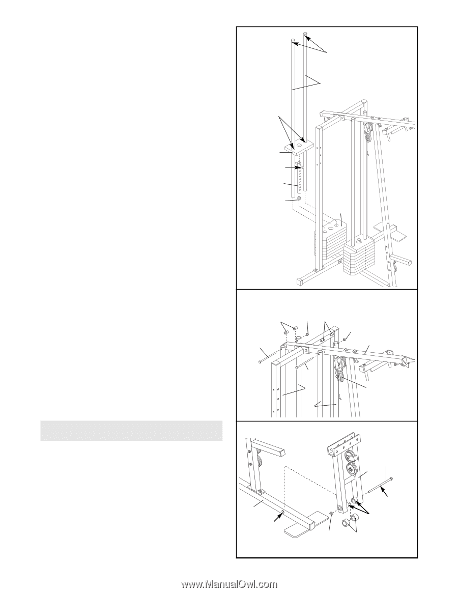
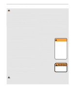
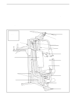
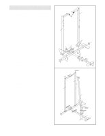
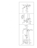
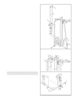
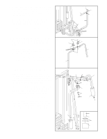
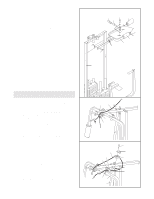
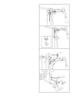
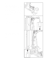
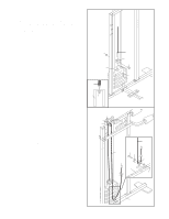
6. Press a Weight Tube Bumper (64) into the end of the other Weight Tube (63). Insert the Weight Tube into the rear stack of Weights (25). Be sure that the pins on the Weight Tube are sitting in the pin grooves in the top Weight (refer to step 4). Lubricate the inside of the holes in the other Top Weight (65). Set the Top Weight onto the rear stack of Weights (25). Insert both Short Weight Guides (73) into the stack of Weights. Be sure that the holes in the Weight Guides are at the top, as shown. 6 Lubricate 65 Pin 63 64 Holes 73 25 7. Attach the upper ends of the Long Weight Guides (62) to the Top Frame (55) with a 5/16" x 6" Bolt (60), two 1/2" x 3/4" Spacers (61), and a 5/16" Nylon Locknut (3). Be sure that the Pulley Bracket (20) is in front of the right Long Weight Guide, as shown. Attach the upper ends of the Short Weight Guides (73) to the Top Frame (55) with a 5/16" x 6" Bolt (60), two 1/2" x 3/4" Spacers (61), and a 5/16" Nylon Locknut (3). 7 61 60 ARM ASSEMBLY 8 8. Press a 1" x 7/8" Plastic Bushing (90) onto each welded spacer on the Press Frame (17). Slide the Press Frame into place onto the Base (4). Note: This will be a tight fit. The Plastic Bushings should fit on each end of the indicated tube in the Base. Make sure that the pulleys are on the side shown. Lubricate the 3/8" x 8" Bolt (59). Attach the Press Frame (17) to the Base (4) with the Bolt and a 3/8" Nylon Locknut (21). 4 Tube 8 3 61 3 55 60 73 20 62 59 17 Lubricate Welded Spacers 21 90
-
 1
1 -
2
-
 3
3 -
 4
4 -
 5
5 -
 6
6 -
 7
7 -
 8
8 -
 9
9 -
 10
10 -
 11
11 -
 12
12 -
 13
13 -
14
-
15
-
16
-
17
-
18
-
19
-
20
-
21
-
22
-
23
-
24
-
25
-
26
-
27
 |
 |