Weider 3550 User Manual - Page 6
Frame Assembly - parts
 |
View all Weider 3550 manuals
Add to My Manuals
Save this manual to your list of manuals |
Page 6 highlights
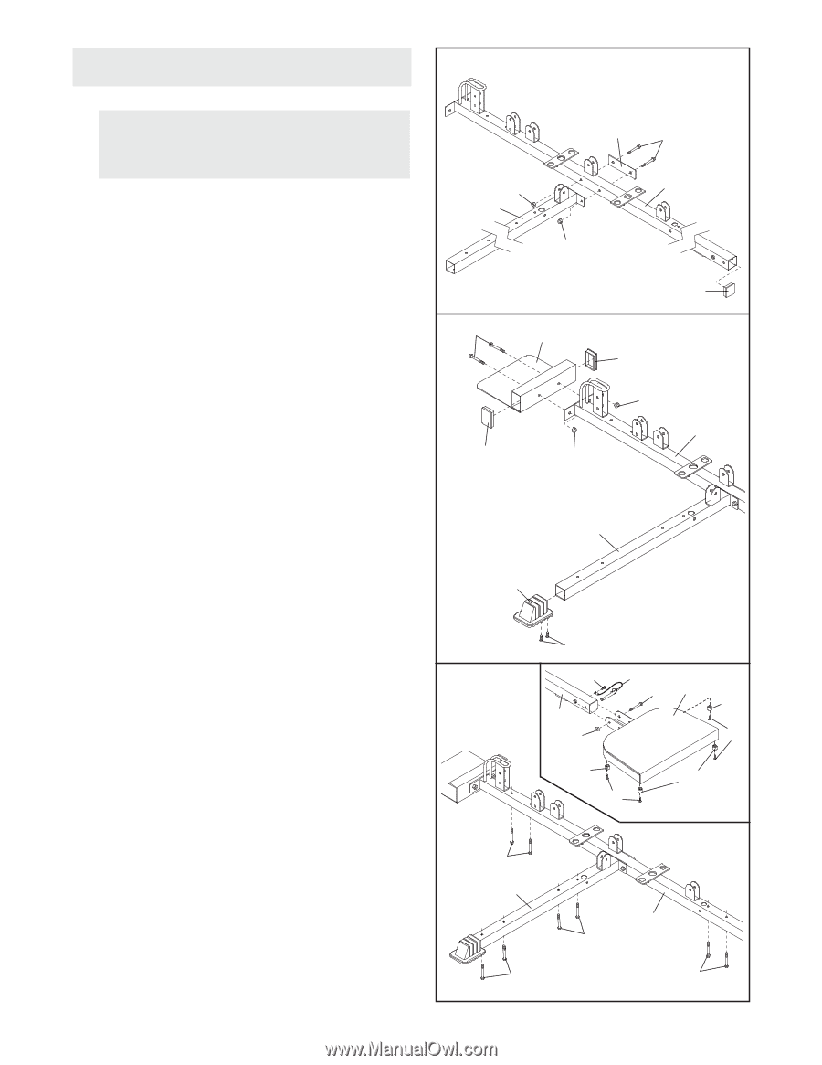
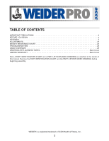
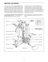
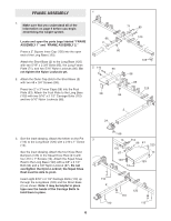
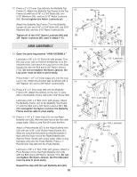
FRAME ASSEMBLY 1 1. Make sure that you understand all of the information on page 5 before you begin assembling the weight system. Locate and open the parts bags labeled "FRAME ASSEMBLY 1" and "FRAME ASSEMBLY 2." Press a 2" Square Inner Cap (105) into the open end of the Long Base (120). Attach the Short Base (2) to the Long Base (120) with two 5/16" x 2 3/4" Bolts (85), the Long Frame Plate (71), and two 5/16" Nylon Locknuts (86). Do not tighten the Nylon Locknuts yet. 2. Attach the Outer Cap (24) to the Short Base (2) with two #8 x 3/4" Screws (98). Press two 2" x 3" Inner Caps (58) into the Foot Plate (53). Attach the Foot Plate to the Long Base (120) with two 5/16" x 2 1/2" Carriage Bolts (110) and two 5/16" Nylon Locknuts (86). 71 85 86 120 2 86 2 110 58 53 86 105 58 86 120 2 24 3. See the inset drawing. Attach the tether on the Pin (112) to the Long Base (120) with a #10 x 1" Screw (14). See the inset drawing. Attach the four Knee Rest Bumpers (123) to the Squat Knee Rest (41) with four #10 x 1" Screws (14). Attach the Squat Knee Rest to the Long Base (120) with a 3/8" x 3 1/4" Bolt (96) and a 3/8" Nylon Locknut (87). Do not overtighten the Nylon Locknut; the Squat Knee Rest must be able to pivot. Insert eight 5/16" x 2 1/2" Carriage Bolts (110) up through the Long Base (120) and the Short Base (2) as shown. Note: It may be helpful to place tape over the heads of the Carriage Bolts to hold them in place. 98 3 14 112 96 41 123 120 87 14 123 123 14 110 2 110 120 110 110 6
-
 1
1 -
 2
2 -
 3
3 -
 4
4 -
 5
5 -
 6
6 -
 7
7 -
 8
8 -
 9
9 -
 10
10 -
 11
11 -
 12
12 -
13
-
14
-
15
-
16
-
17
-
18
-
19
-
20
-
21
-
22
-
23
-
24
-
25
-
26
-
27
-
28
-
29
-
30
-
31
-
32
-
33
 |
 |