Weider 8525 English Manual - Page 10
Attach the V-pulley and a Long Cable Trap
 |
View all Weider 8525 manuals
Add to My Manuals
Save this manual to your list of manuals |
Page 10 highlights
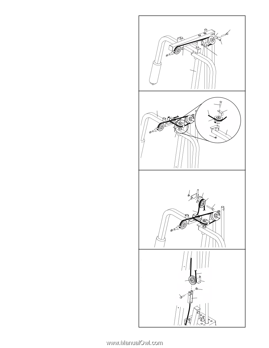
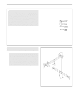
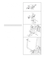
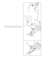
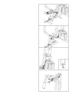
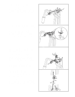
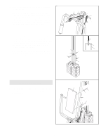
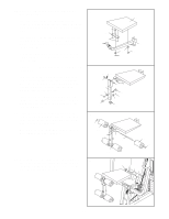
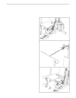
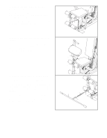
15. Wrap the Long Cable (23) around a "V"-Pulley 15 (6). Attach the "V"-Pulley and a Long Cable Trap (50) to the indicated bracket on the Front Upright (42) with a 3/8" x 2 1/2" Bolt (7) and a 3/8" Nylon Locknut (21). Make sure that the Long Cable Trap is positioned to hold the Cable in place. 23 42 6 7 50 21 16. Route the Long Cable (23) around a "V"-pulley (6). Attach the "V"-pulley and a Long Cable Trap (50) to the Left Arm (47) with a 3/8" x 2 1/2" Bolt (7) and a 3/8" Nylon Locknuts (21). Make sure that the Long Cable Trap is positioned to hold the Cable in the groove of the "V"-pulley. Repeat this step with the Right Arm (48). 16 48 47 7 23 50 6 47 21 17. Note: The 3 1/2" Pulley (15) in this step has 17 been preassembled. It is shown exploded in this drawing for clarity. Route the Long Cable (23) around the 3 1/2" Pulley (15) attached to the Pulley Bracket (20). Make sure that the Cable is in the groove of the Pulley and that the Cable Trap (66) is turned to hold the Cable in place. Tighten the 3/8" x 2" Bolt (12) and the 3/8" Nylon Locknut (21). Make sure that the 5/16" x 5" Bolt (not shown) is properly tightened and that the Pulley Bracket (20) can move freely. 18. Attach a 3 1/2" Pulley (15) and a Cable Trap (66) 18 to the indicated hole in the Long "U"-bracket (57) with a 3/8" x 2" Bolt (12) and a 3/8" Nylon Locknut (21). Make sure that the Cable Trap is inside of the "U"-bracket. Route the Long Cable (23) between the 3 1/2" Pulley (15) and the Cable Trap (66). Make sure that the Cable is in the groove of the Pulley and that the Cable and Pulley move smoothly. 21 20 23 66 15 12 15 12 23 66 21 57 10
-
 1
1 -
2
-
3
-
4
-
 5
5 -
 6
6 -
 7
7 -
 8
8 -
 9
9 -
 10
10 -
 11
11 -
 12
12 -
 13
13 -
 14
14 -
 15
15 -
16
-
17
-
18
-
19
-
20
-
21
-
22
-
23
 |
 |