Weider 8525 English Manual - Page 7
Arm Assembly
 |
View all Weider 8525 manuals
Add to My Manuals
Save this manual to your list of manuals |
Page 7 highlights
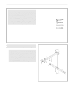
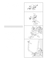
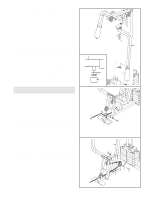
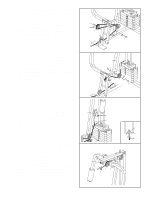
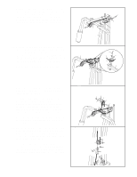
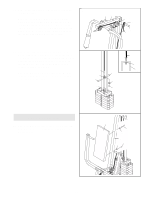
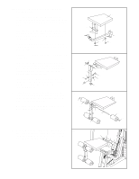
4. Press two 2" Square Inner Caps (27) into the indi- 4 cated ends of the Top Frame (55). Press two 1 3/4" Square Inner Caps (44) into the ends of the crossbar on the Top Frame. Press two Round 44 Inner Caps (78) into the top of the crossbar. 78 55 27 5. Attach the Top Frame (55) to the Front Upright (42) with two 5/16" x 2 3/4" Bolts (11), two 5/16" Washers (8), and two 5/16" Nylon Locknuts (3). Attach the upper ends of the Weight Guides (62) to the Top Frame (55) with a 5/16" x 6" Bolt (60) and a 5/16" Nylon Locknut (3). Tighten the 5/16" Nylon Locknuts (3) used in steps 2 and 5. Arm Assembly 6. Press two 1" x 7/8" Plastic Bushing (75) onto the welded spacers on the Press Frame (17). Slide the Press Frame into place on the Base (4) as shown. Note: This will be a tight fit. The Plastic Bushings should fit onto each end of the indicated tube in the Base. Lubricate the 3/8" x 8" Bolt (59) with grease. Attach the Press Frame (17) to the Base (4) with the Bolt and a 3/8" Nylon Locknut (21). Do not overtighten the Locknut; the Press Frame must be able to pivot easily. 7. Press a 1 3/4" Square Inner Cap (44) into the top of a Press Arm (46). Press two 1" Round Inner Caps (49) into the ends of the handle on the Press Arm. Attach the Press Arm (46) to one side of the Press Frame (17) with two 5/16" x 2 1/2" Bolts (22) and two 5/16" Nylon Locknuts (3). Assemble the other Press Arm (46) in the same manner. 27 Crossbar 5 11 8 55 3 42 6 17 44 8 3 60 62 21 Welded Spacer 75 4 Tube 7 49 44 49 Lubricate 59 46 46 22 3 17 7
-
 1
1 -
 2
2 -
 3
3 -
 4
4 -
 5
5 -
 6
6 -
 7
7 -
 8
8 -
 9
9 -
 10
10 -
 11
11 -
 12
12 -
13
-
14
-
15
-
16
-
17
-
18
-
19
-
20
-
21
-
22
-
23
 |
 |
