Weider 8525 English Manual - Page 9
Pulley 15. Attach the Pulley and a Cable Trap
 |
View all Weider 8525 manuals
Add to My Manuals
Save this manual to your list of manuals |
Page 9 highlights
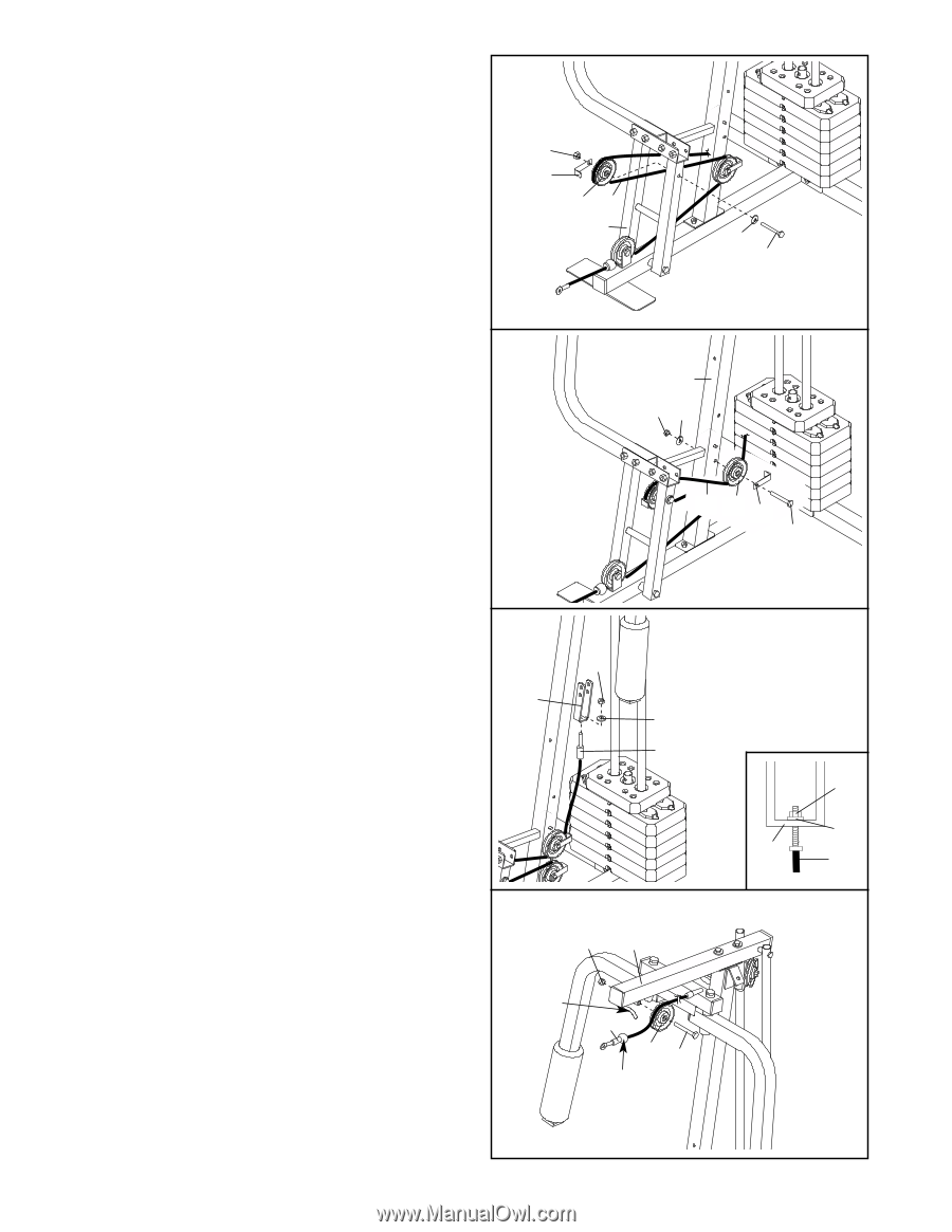
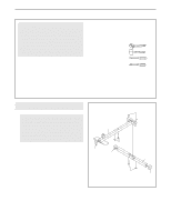
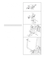
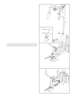
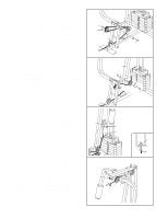
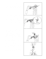
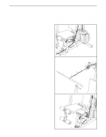
11. Note: The 3 1/2" Pulley (15) in this step has been preassembled. It is shown exploded in this drawing for clarity. Route the Short Cable (58) around the 3 1/2" Pulley (15) attached to the Press Frame (17). Make sure that the Cable Trap (66) is turned to hold the Cable in place and that the Cable is routed around the Pulley as shown. Tighten the 3/8" Nylon Locknut (21), 3/8" Washer (9), and the 3/8" x 3 1/2" Bolt (16). 11 21 66 15 58 17 9 16 12. Route the Short Cable (58) around the 3 1/2" 12 Pulley (15). Attach the Pulley and a Cable Trap (66) to the upper hole in the Front Upright (42) with a 3/8" x 3 3/4" Bolt (71), a 3/8" Washer (9), and a 3/8" Nylon Locknut (21). Make sure that the Cable Trap is turned to hold the Cable in place and that the Cable is routed around the Pulley as shown. 42 21 9 58 15 66 71 13. Remove the preassembled 3 1/2" Pulley (not shown) from the Long "U"-bracket (57). Attach the end of the Short Cable (58) to the Long "U"-bracket (57) with a 1/4" Nylon Locknut (2) and a 1/4" Washer (10). See the inset drawing. Do not overtighten the Nylon Locknut; it should be threaded onto the end of the Cable so only a couple of threads are showing above the nut. 13 57 2 10 58 14. Note: The 3 1/2" Pulley (15) in this step has been preassembled. It is shown exploded in this drawing for clarity. Locate the Long Cable (23). Route the Long Cable around the indicated 3 1/2" Pulley (15) attached to the Top Frame (55). Make sure that the Cable is between the Pulley and the hook and that the end of the Cable with the ball is on the indicated side of the hook. Tighten the 3/8" x 3 3/4" Bolt (71) and the 3/8" Nylon Locknut (21). 14 21 55 Hook 23 15 71 Ball 2 10 57 58 9
-
 1
1 -
2
-
3
-
 4
4 -
 5
5 -
 6
6 -
 7
7 -
 8
8 -
 9
9 -
 10
10 -
 11
11 -
 12
12 -
 13
13 -
 14
14 -
15
-
16
-
17
-
18
-
19
-
20
-
21
-
22
-
23
 |
 |