Weider 8525 English Manual - Page 8
Cable Assembly - pulley
 |
View all Weider 8525 manuals
Add to My Manuals
Save this manual to your list of manuals |
Page 8 highlights
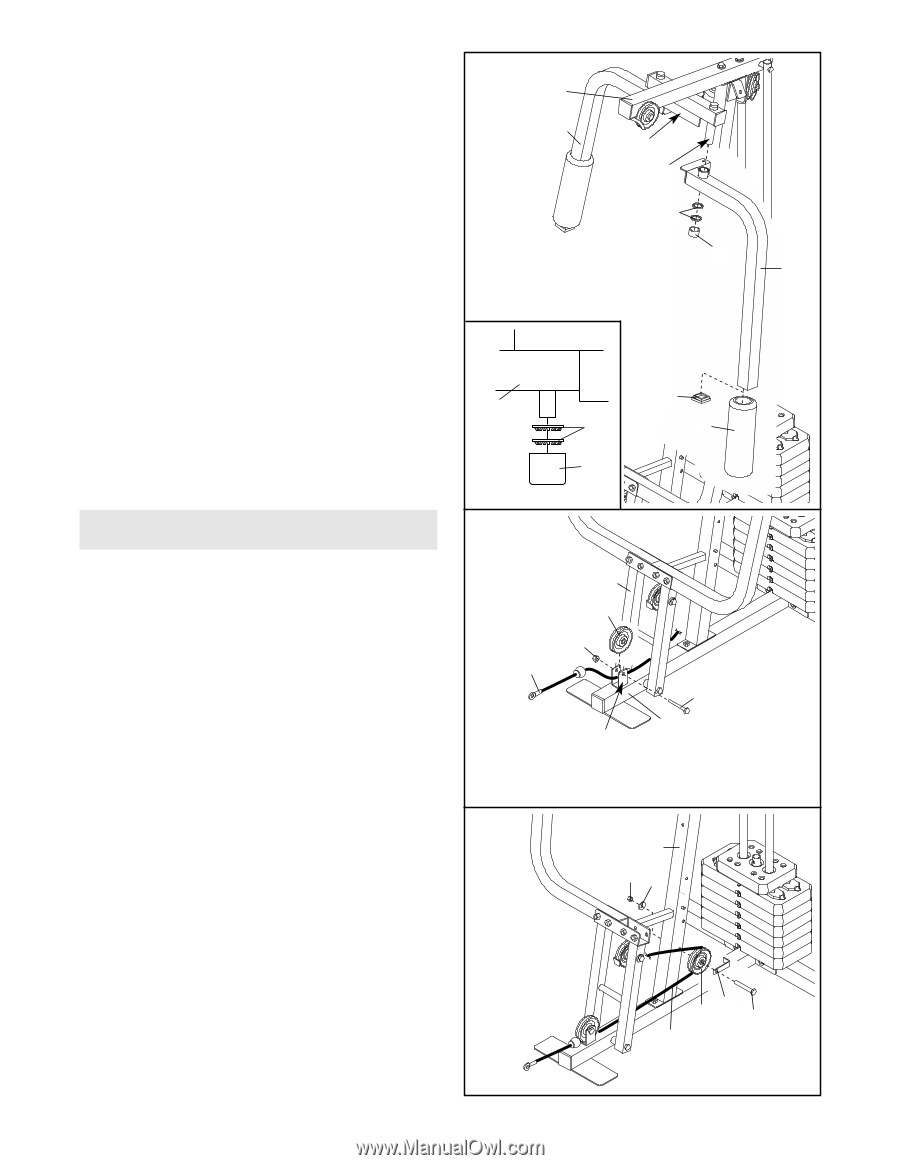
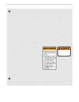
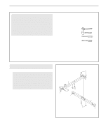
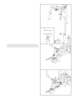
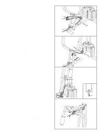
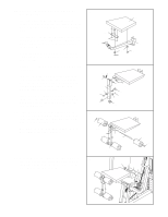
8. Identify the Right Arm (48) and the Left Arm (47) 8 by the position of the welded bracket on each Arm. Lubricate both axles on the Top Frame (55). Press a 1 3/4" Square Inner Cap (44) into the lower end of the Left Arm (47). Wet the end of the Arm with soapy water and slide a 10" Pad (45) onto it. 55 48 Bracket Lubricate Axle 69 Have another person slide the Left Arm (47) onto the left axle on the Top Frame (55). Note: Be careful not to confuse the Right Arm (48) with the Left Arm. Make sure that the upper end of the Left Arm is behind the indicated bracket on the Top Frame. 70 47 Tap two 1" Retainers (69) and a 1" Round Cover Cap (70) onto the right axle. Make sure that the teeth on the Retainers bend toward the Cover 55 Cap, as shown in the inset drawing. 44 69 45 Attach the Right Arm (48) in the same manner. 70 Cable Assembly 9. During steps 9 through 20, refer to the CABLE DIAGRAM on page 18 of this manual to verify proper cable routing. Locate the Short Cable (58). Lay the Cable in the bracket on the Base (4) and under the Press Frame (17). Attach a 3 1/2" Pulley (15) to the bracket with a 3/8" x 2" Bolt (12) and a 3/8" Nylon Locknut (21). Make sure that the end of the Cable with the ball is on the indicated side of the bracket. 9 17 15 21 58 Bracket 12 4 10. Route the Short Cable (58) around a 3 1/2" Pulley 10 (15). Attach the Pulley and a Cable Trap (66) to the lower hole in the Front Upright (42) with a 3/8" x 3 3/4" Bolt (71), a 3/8" Washer (9), and a 3/8" Nylon Locknut (21). Make sure that the Cable Trap is turned to hold the Cable in place and that the Cable is routed around the Pulley as shown. 42 21 9 15 66 71 58 8
-
 1
1 -
2
-
 3
3 -
 4
4 -
 5
5 -
 6
6 -
 7
7 -
 8
8 -
 9
9 -
 10
10 -
 11
11 -
 12
12 -
 13
13 -
14
-
15
-
16
-
17
-
18
-
19
-
20
-
21
-
22
-
23
 |
 |