Weider 9350 Instruction Manual - Page 11
Cable Assembly
 |
View all Weider 9350 manuals
Add to My Manuals
Save this manual to your list of manuals |
Page 11 highlights
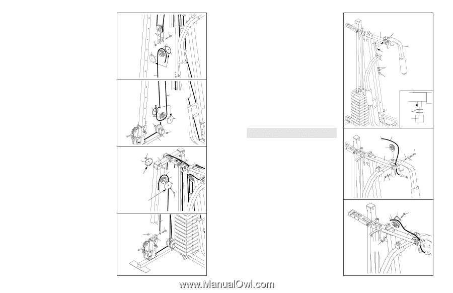
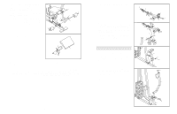
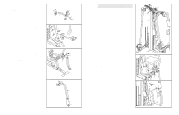
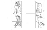
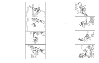
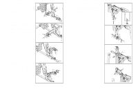
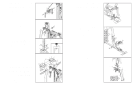
41. Wrap the Carriage Cable (83) around a 90mm 41 Pulley (15). Attach the Pulley and a pair of Pulley Covers (40) to the first set of holes from the bot- tom of the two Large Pulley Plates (91) with an M10 x 52mm Bolt (12) and an M10 Nylon Locknut (21). Make sure the small tabs on the Pulley Covers are on bottom. 42. Wrap the Carriage Cable (83) under a 90mm 42 Pulley (15). Attach the Pulley and a pair of Pulley Covers (40) inside the other bracket on the Stabiliser (5) with the M10 x 105mm Bolt (106) used in step 40, and an M10 Nylon Locknut (21). Make sure the small tabs on the Pulley Covers are on top. 43. Wrap the Carriage Cable (83) around a 90mm 43 Pulley (15). Attach the Pulley and a pair of Pulley Covers (40) inside the bracket on the Right Upright Bracket (93) with an M10 x 52mm Bolt (12) and an M10 Nylon Locknut (21). Make sure the small tabs on the Pulley Covers are on the bottom. 12 91 21 15 40 40 Small 83 Tab 83 Small 40 Tab 15 40 106 21 5 21 93 40 Small Tab 83 15 40 44. Attach the Carriage Cable (83) to the Carriage 44 (89) with an M10 x 22mm Bolt (98) and an M10 Nylon Locknut (21). Small Tab 21 12 83 98 89 18 15. Lubricate the axles on the Top Frame (55) with 15 grease. Orient the Right Butterfly Arm (48) as shown and slide it onto the right axle. Make sure the Butterfly Arm is behind the bracket on the Top Frame. Have a second person secure the Right Butterfly Arm (48) to the axle with two 25mm Retainers (68) and a 25mm Cover Cap (65). Note: Place the Retainers on top of the inverted Cover Cap, as shown in the inset drawing; make sure the teeth on the Retainers bend toward the Cover Cap. Gently tap the Cover Cap onto the axle. Repeat this step with the Left Butterfly Arm (47). Cable Assembly 16 16. For cable identification and routing during steps 16 to 44, refer to the CABLE DIAGRAMS on page 25. Do not overtighten the locknuts securing the pulley; the pulleys must be able to roll easily. Locate the High Cable (11), which has a ball on one end and an eyelet on the other. Route the eyelet end of the Cable up through the Top Frame (55) and around a "V"-pulley (6). Attach the "V"pulley inside the Top Frame with an M10 x 78mm Bolt (76), two 12.5mm Spacers (82), two M10 Washers (9), and an M10 Nylon Locknut (21). 17 17. Wrap the High Cable (11) around a "V"-pulley (6). Attach the "V"-pulley and a Long Cable Trap (50) to the bracket on the Top Frame (55) with an M10 x 60mm Bolt (7) and an M10 Nylon Locknut (21). Make sure the Cable Trap is oriented to hold the Cable in the groove of the "V"-pulley. 55 Bracket 47 Lubricate Axle 48 68 65 Axle 68 65 11 6 76 55 82 9 82 21 9 50 6 7 11 55 21 11
-
 1
1 -
2
-
3
-
4
-
5
-
 6
6 -
 7
7 -
 8
8 -
 9
9 -
 10
10 -
 11
11 -
 12
12 -
 13
13 -
 14
14 -
 15
15 -
 16
16 -
17
-
18
 |
 |