Weider 9350 Instruction Manual - Page 9
Arm Assembly
 |
View all Weider 9350 manuals
Add to My Manuals
Save this manual to your list of manuals |
Page 9 highlights
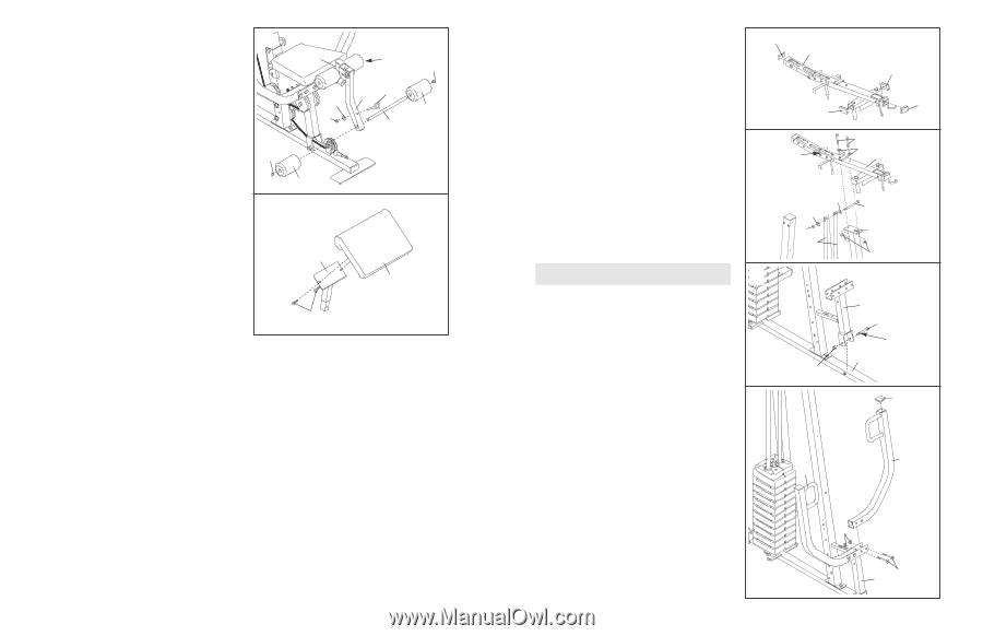
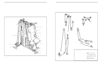
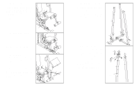
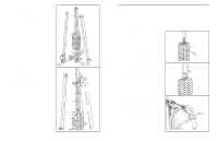
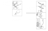
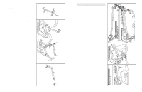
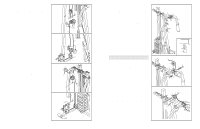
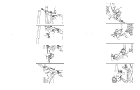
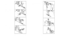
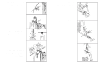
48. Slide a Pad Tube (28) through the hole in the Leg 48 Lever (29). Press two 19mm Round Inner Caps (34) into the ends of the Pad Tube. Slide two Foam Pads (30) onto the Pad Tube. Repeat this step with the other Pad Tube (28) and the Seat Frame (36). Orient the Eyebolt (109) as shown. Attach the Eyebolt to the Leg Lever (29) with an M10 Nylon Locknut (21) and an M10 Washer (9). Note: Make sure that Eyebolt is positioned vertically on the Leg Lever. 34 49. Attach the Curl Pad (24) to the Curl Post (35) with 49 two M6 x 16mm Bolts (18). 36 28 34 109 29 9 30 21 28 30 35 24 18 50. Make sure that all parts have been properly tightened. The use of the remaining parts will be explained in ADJUSTMENTS, beginning on the following page. Before using the weight system, pull each cable a few times to make sure that the cables move smoothly over the pulleys. If one of the cables does not move smoothly, find and correct the problem. IMPORTANT: If the cables are not properly installed, they may be damaged when heavy weight is used. See the CABLE DIAGRAMS on page 25 for proper cable routing. If there is any slack in the cables, you will need to remove it by tightening the cables; see TROUBLESHOOTING AND MAINTENANCE on page 24. 20 7. Press four 40mm x 60mm Inner Caps (27) into the ends of the Top Frame (55). 7 27 55 27 27 27 8. Hold the Top Frame (55) on top of the Front 8 Upright (42) and between the Weight Guides (62). Attach the Top Frame to the Front Upright with two M10 x 60mm Bolts (7), two M10 Washers (9), and two M10 Nylon Locknuts (21). Do not tight- en the Locknuts yet. Attach the Weight Guides (62) to the indicated tube on the Top Frame (55) with an M10 x 155mm Bolt (60), two M10 Washers (9), and an M10 Nylon Locknut (21). Arm Assembly 9 Tube 7 9 55 9 60 9 21 42 62 21 9. Lubricate the M10 x 98mm Bolt (16) with grease. Attach the Press Frame (17) to the Base (4) with the Bolt and an M10 Nylon Locknut (21). Do not overtighten the Locknut; the Press Frame must be able to pivot easily. 10. Press a 50mm Square Inner Cap (44) into the top 10 of a Press Arm (46). Attach the Press Arm to the Press Frame (17) with two M10 x 70mm Bolts (22) and two M10 Nylon Locknuts (21). Repeat this step with the other Press Arm (46). 17 16 Lubricate 4 21 44 46 46 21 22 17 9
-
 1
1 -
2
-
3
-
 4
4 -
 5
5 -
 6
6 -
 7
7 -
 8
8 -
 9
9 -
 10
10 -
 11
11 -
 12
12 -
 13
13 -
 14
14 -
15
-
16
-
17
-
18
 |
 |