Weider 9350 Instruction Manual - Page 14
M10 x 52mm Bolt 12 and an M10 Nylon Locknut
 |
View all Weider 9350 manuals
Add to My Manuals
Save this manual to your list of manuals |
Page 14 highlights
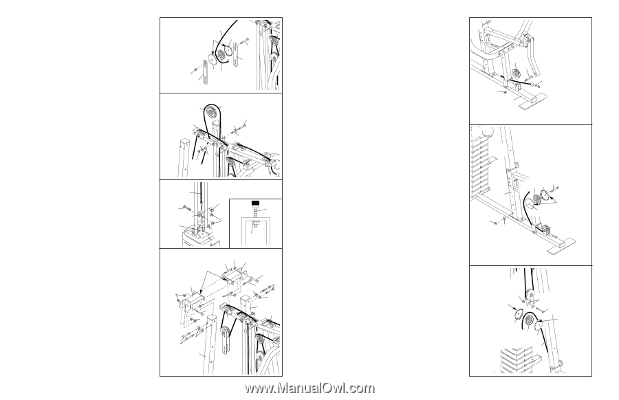
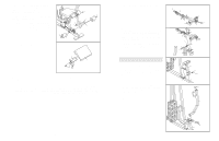
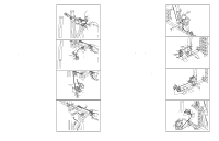
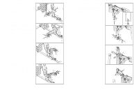
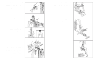
26. Wrap the Weight Cable (23) under a 90mm Pulley 26 (15). Attach the Pulley and a pair of Pulley Covers (40) to the second set of holes from the top of the two Large Pulley Plates (91) with an M10 x 52mm Bolt (12) and an M10 Nylon Locknut (21). Make sure the small tabs on the Pulley Covers are on top. 27. Route the Weight Cable (23) up through the Top 27 Frame (55), around the 115mm Pulley (74), and back down through the Top Frame. Attach the Pulley inside the Top Frame with an M10 x 78mm Bolt (76), two 17.5mm Spacers (77), two M10 Washers (9), and an M10 Nylon Locknut (21). 23 Small Tabs 40 12 91 21 91 40 15 74 55 23 76 9 77 9 77 21 28. Attach the Weight Cable (23) to the "U"-bracket (57) with an M8 Washer (70) and an M8 Nylon Locknut (3). Do not completely tighten the Locknut; it should be threaded only two turns onto the end of the Cable, as shown in the inset drawing. Attach the "U"-bracket (57) to the Weight Tube (63) with an M8 x 45mm Bolt (66) and an M8 Nylon Locknut (3). 28 23 66 57 63 70 23 3 3 29. Have another person hold the Right and Left Upright Brackets (93, 94) between the Top Frame (55), the Carriage Upright (84) and the Support Upright (88). The indicated holes in the Upright Brackets should fit over the M10 x 78mm Bolt (not shown) and the M10 Nylon Locknut (21) used in step 25. Attach the Upright Brackets (93, 94) to the Top Frame (55) with two M10 x 80mm Bolts (8) and two M10 Nylon Locknuts (21). Do not tighten the Locknuts yet. Attach the Right Upright Bracket (93) to the Carriage Upright (84) with three M10 x 80mm Bolts (8), two M10 Washers (9), and two M10 Nylon Locknuts (21). Attach the Left Upright Bracket (94) to the Support Upright (88) in the same way. 29 21 8 21 94 Hole 8 93 21 8 8 9 9 8 21 21 88 55 9 8 84 Tighten the M10 Nylon Locknuts (21) used in step 2, 3, 8, and 29. 14 30. Locate the Low Cable (69), which has a ball on 30 one end. Rest the Cable in the bracket on the Base (4). Attach a High Quality Pulley (14) inside the bracket with an M10 x 45mm Bolt (100) and an M10 Nylon Locknut (21). 14 100 69 21 4 31. Wrap the Low Cable (69) around a 90mm Pulley 31 (15). Attach the Pulley and a pair of Pulley Covers (40) to the bottom hole in the Front Upright (42) with an M10 x 110mm Bolt (64), an M10 Washer (9), and an M10 Nylon Locknut (21). Make sure the large tabs on the Pulley Covers are on the side shown. 42 21 9 15 40 64 Large Tab 40 69 32. Wrap the Low Cable (69) around a 90mm Pulley 32 (15). Attach the Pulley and a pair of Pulley Covers (40) to the Pulley Plates (58) with an M10 x 52mm Bolt (12) and an M10 Nylon Locknut (21). Make sure the large tabs on the Pulley Covers are on top. 21 Large Tab 40 58 12 Large Tab 15 40 69 15
-
 1
1 -
2
-
3
-
4
-
5
-
6
-
7
-
8
-
 9
9 -
 10
10 -
 11
11 -
 12
12 -
 13
13 -
 14
14 -
 15
15 -
 16
16 -
 17
17 -
 18
18
 |
 |