Weider 9350 Instruction Manual - Page 6
Frame Assembly
 |
View all Weider 9350 manuals
Add to My Manuals
Save this manual to your list of manuals |
Page 6 highlights
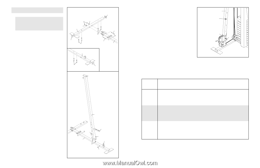
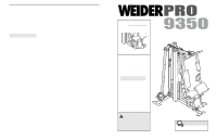
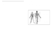
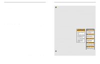
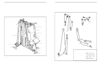
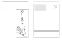
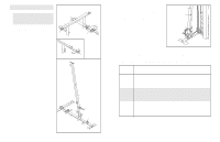
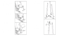
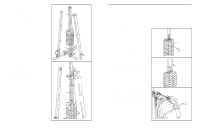
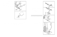
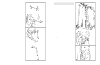
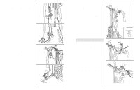
FRAME ASSEMBLY 1. Before beginning assembly, make sure you have read and understood the information in the box on page 5. This introduction will save you more time than it takes to read it. Press a 40mm x 60mm Outer Cap (10) onto the end of the Stabiliser (5). Press two 40mm x 60mm Inner Caps (27) into the ends of the Base (4) and the Stabiliser. Insert six M10 x 55mm Carriage Bolts (1) up through the Base (4) and the Stabiliser (5). Place the Base and the Stabiliser flat on the floor. Attach the Base (4) to the Stabiliser (5) with two M10 x 78mm Bolts (76), two M10 Washers (9), and two M10 Nylon Locknuts (21). 2. Press the 25mm Square Inner Cap (97) into the Front Upright (42). Attach the Front Upright (42) to the Base (4) with the two M10 x 55mm Carriage Bolts (1) and two M10 Nylon Locknuts (21). Do not tighten the Locknuts yet. Press two M10 Round Bushings (96) into the Base (4). 1 21 9 5 27 1 4 1 2 10 9 76 1 76 4 27 42 21 4 1 97 21 96 96 6 ADJUSTING THE CARRIAGE To adjust the height of the Carriage (89), turn the Carriage Knob (73) counterclockwise until it is loose, and pull it out as far as possible. Slide the Carriage up or down the Carriage Upright (84) to the desired height. Engage the Carriage Knob into an adjustment hole in the upright and turn the Knob clockwise until it is fully tightened. 84 Adjustment Hole 89 73 WEIGHT RESISTANCE CHART The chart below shows the approximate weight resistance at each exercise station. Top refers to the 6 lb. top weights. The other numbers refer to the 12.5 lb. weight plates. Weight resistance shown for the butterfly arm station is for each butterfly arm. Note: The actual resistance at each station may vary due to differences in individual weight plates as well as friction between the cables, pulleys, and weight guides. Weight Top 1 2 3 4 5 6 7 8 9 10 11 High Pulley (lbs.) 12 21 29 37 45 53 61 69 79 86 96 104 Butterfly Arm (lbs.) 8 15 21 27 34 40 46 53 59 65 71 78 Press Arm (lbs.) Leg Lever (lbs.) Low Pulley (lbs.) 20 21 25 38 39 34 55 56 44 73 74 57 90 91 72 108 109 86 125 126 100 143 144 115 160 161 133 178 179 150 195 196 168 213 214 182 Carriage Pulley (lbs.) 11 26 41 56 71 86 101 116 131 146 161 176 Note: 1 lb = .454 kg 23
-
 1
1 -
 2
2 -
 3
3 -
 4
4 -
 5
5 -
 6
6 -
 7
7 -
 8
8 -
 9
9 -
 10
10 -
 11
11 -
 12
12 -
13
-
14
-
15
-
16
-
17
-
18
 |
 |