Weider Club 8980 W English Manual - Page 14
Attach the Headrest 90 and the Headrest Base
 |
View all Weider Club 8980 W manuals
Add to My Manuals
Save this manual to your list of manuals |
Page 14 highlights
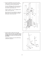
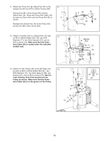
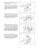
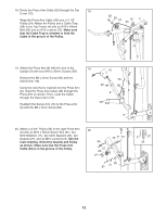
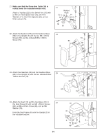
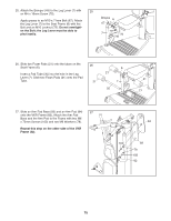
21. Make sure that the Press Arm Cable (30) is routed under the indicated welded rods. Attach a V-pulley (22) to the Swivel Arm (16) with an M10 x 64mm Button Bolt (75), two M10 Washers (71), two 5mm Spacers (25), and an M10 Locknut (73). 21 Welded Rods 73 71 25 16 25 75 71 30 22 22. Attach the Backrest (18) and the Backrest Base 22 (88) to the Upright (3) with the two M6 x 25mm Screws (60) and the indicated M6 x 140mm Screw (79). 88 18 79 60 60 3 23. Attach the Headrest (90) and the Headrest Base 23 (89) to the Upright (3) with the two indicated M6 x 140mm Screws (79). 89 90 3 79 24. Attach the Seat (19) and the Seat Base (91) to 24 the Seat Frame (6) with two M6 x 25mm Screws (60), an M6 x 87mm Screw (68), and an M6 Washer (78). Hook the Seat Frame (6) onto the Upright (3) at the indicated location. 19 91 6 3 78 60 68 14
-
 1
1 -
2
-
3
-
4
-
5
-
6
-
7
-
8
-
 9
9 -
 10
10 -
 11
11 -
 12
12 -
 13
13 -
 14
14 -
 15
15 -
 16
16 -
 17
17 -
 18
18 -
 19
19 -
20
-
21
-
22
-
23
-
24
-
25
-
26
-
27
-
28
 |
 |
